Assembly
For assembly of the setup, make sure you have all parts in hand. You can compare it in the Bill of material. A stop motion video was captured showing dismatle and assemble the whole setup.
- Inventor Explosion
- Design Files
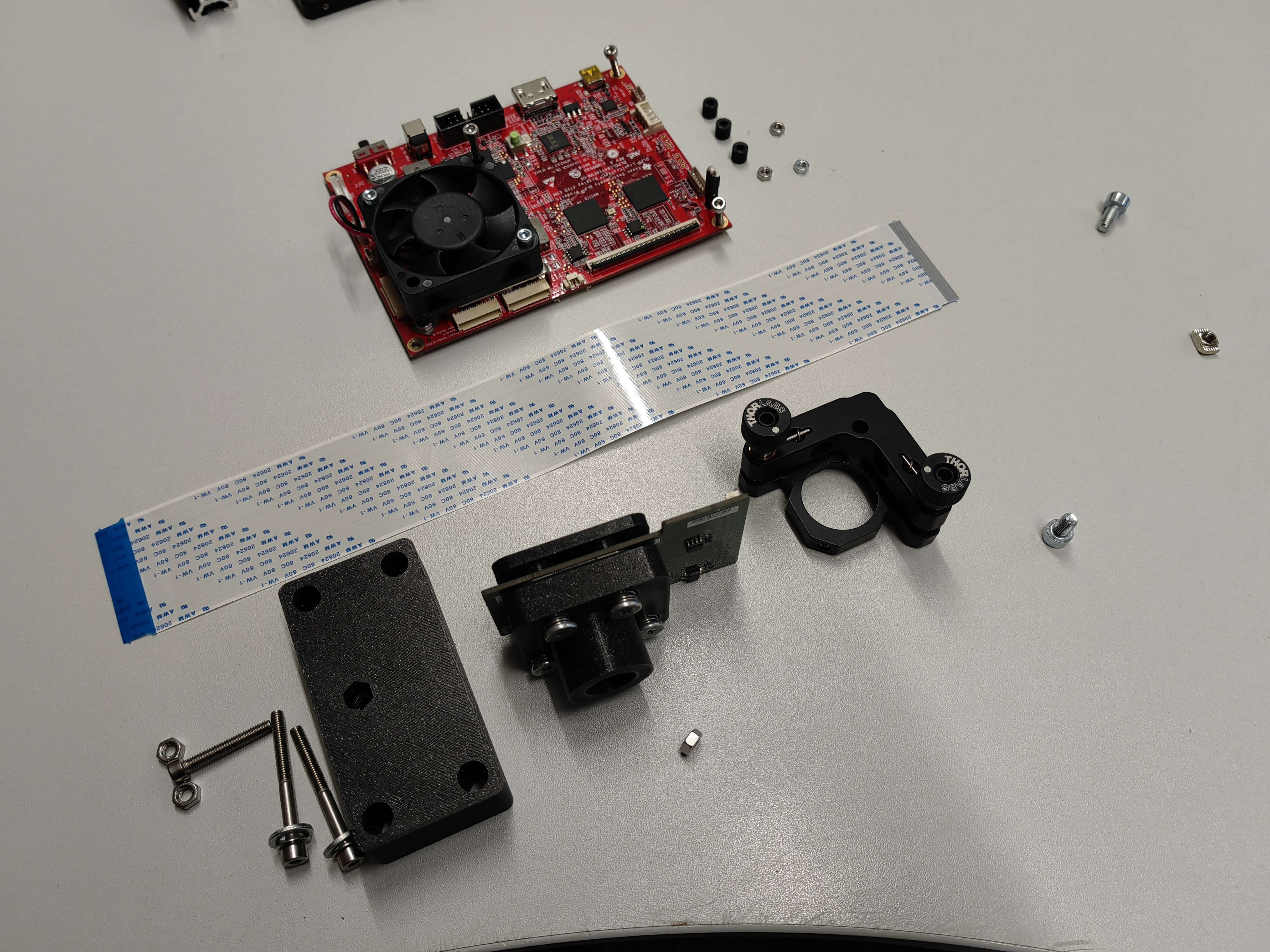
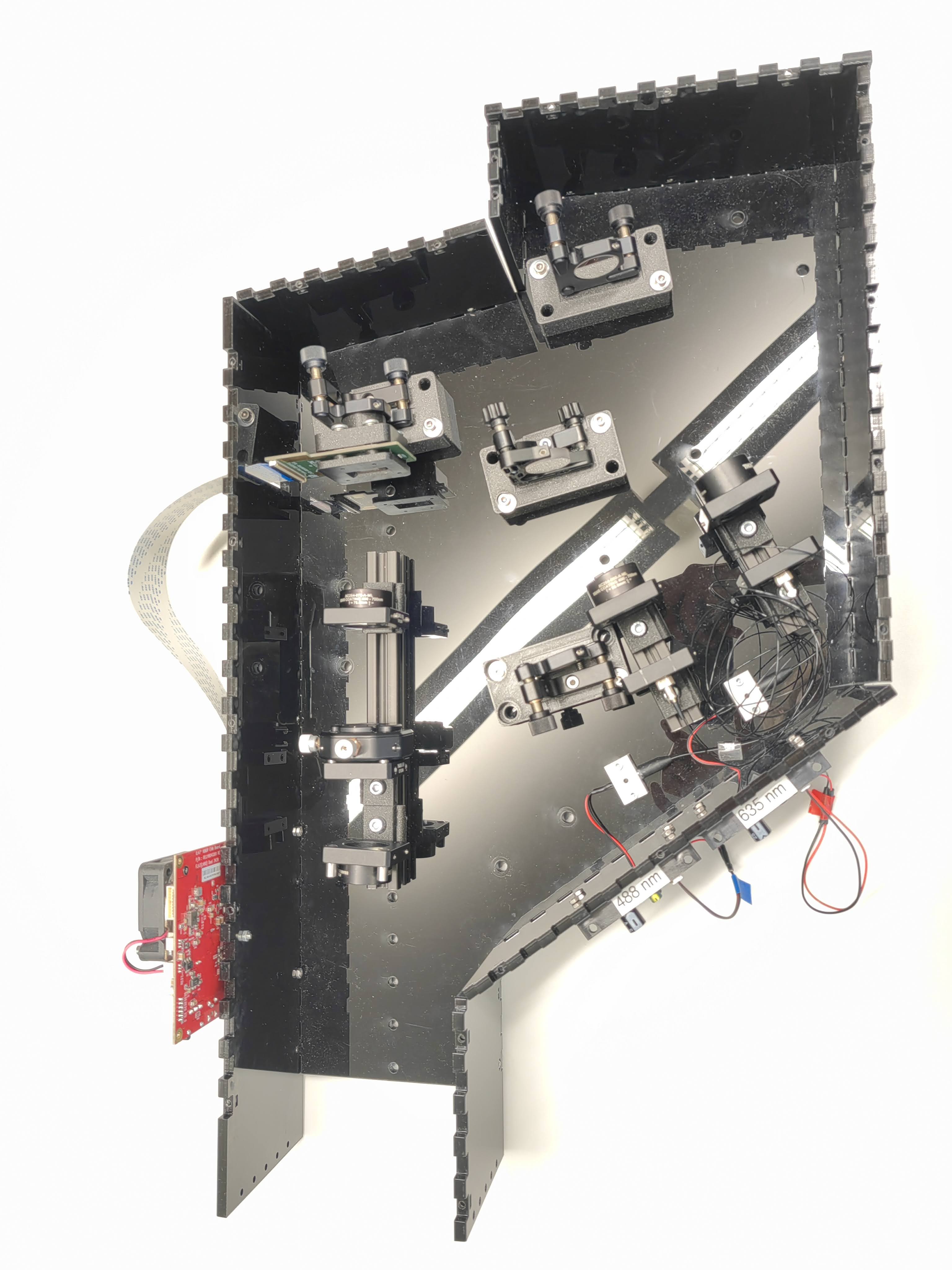
Explosion view
All required components for a SIM extension kit is shwon in this image. We used lots of 3D printed parts to replace the thorlabs optomechanics, the files can be found in this link. The enclosure of the setup is 6mm black plexi glass fabricated with laser cutter, the CAD file is save in this link.
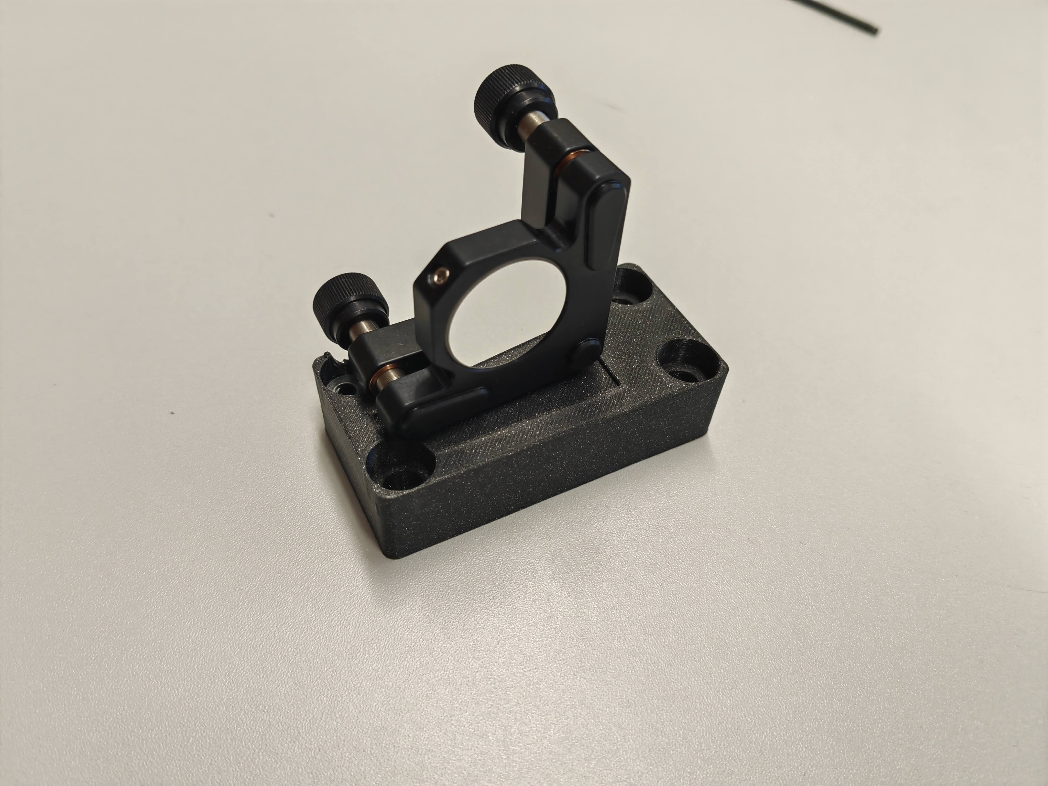
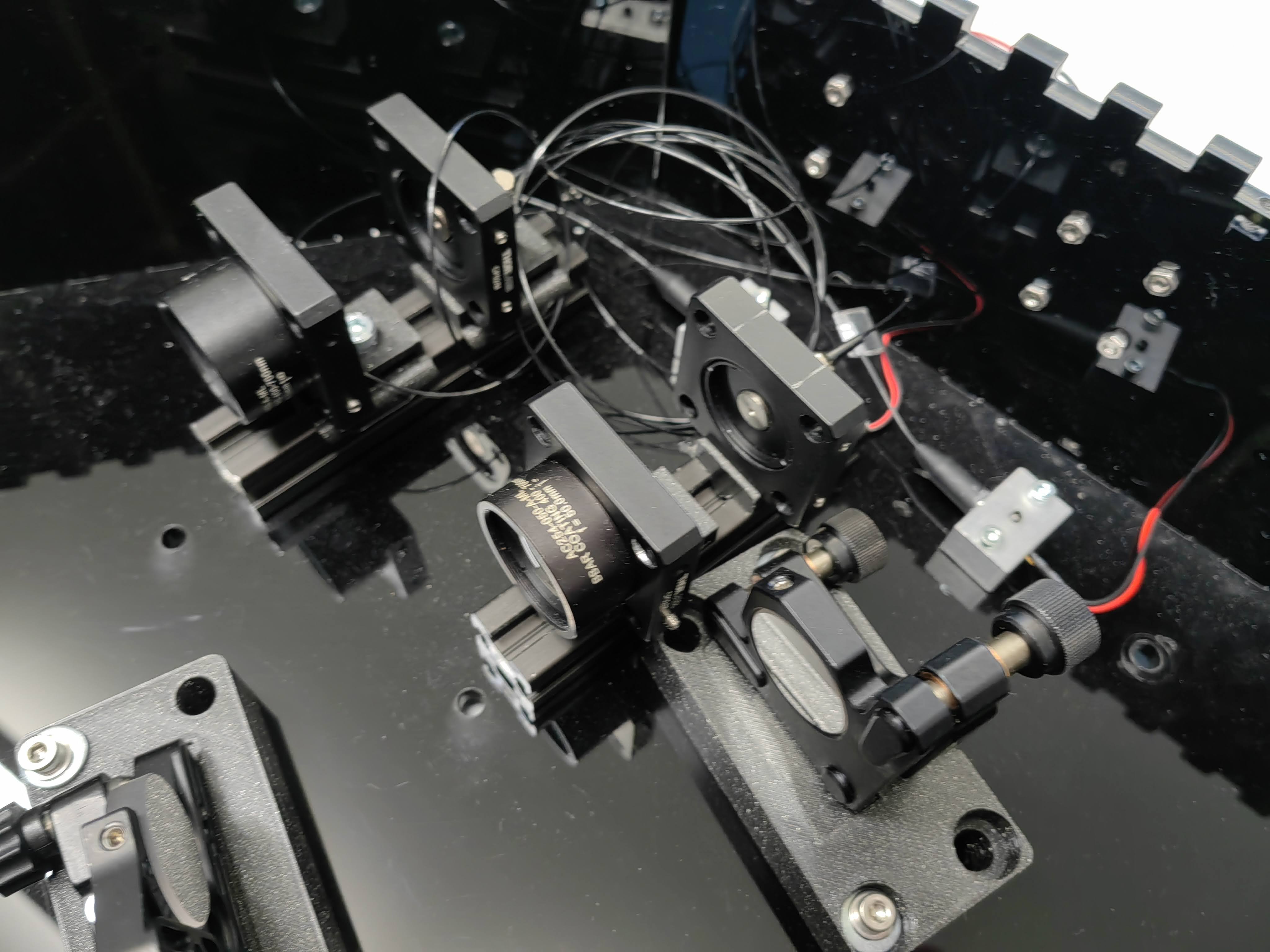
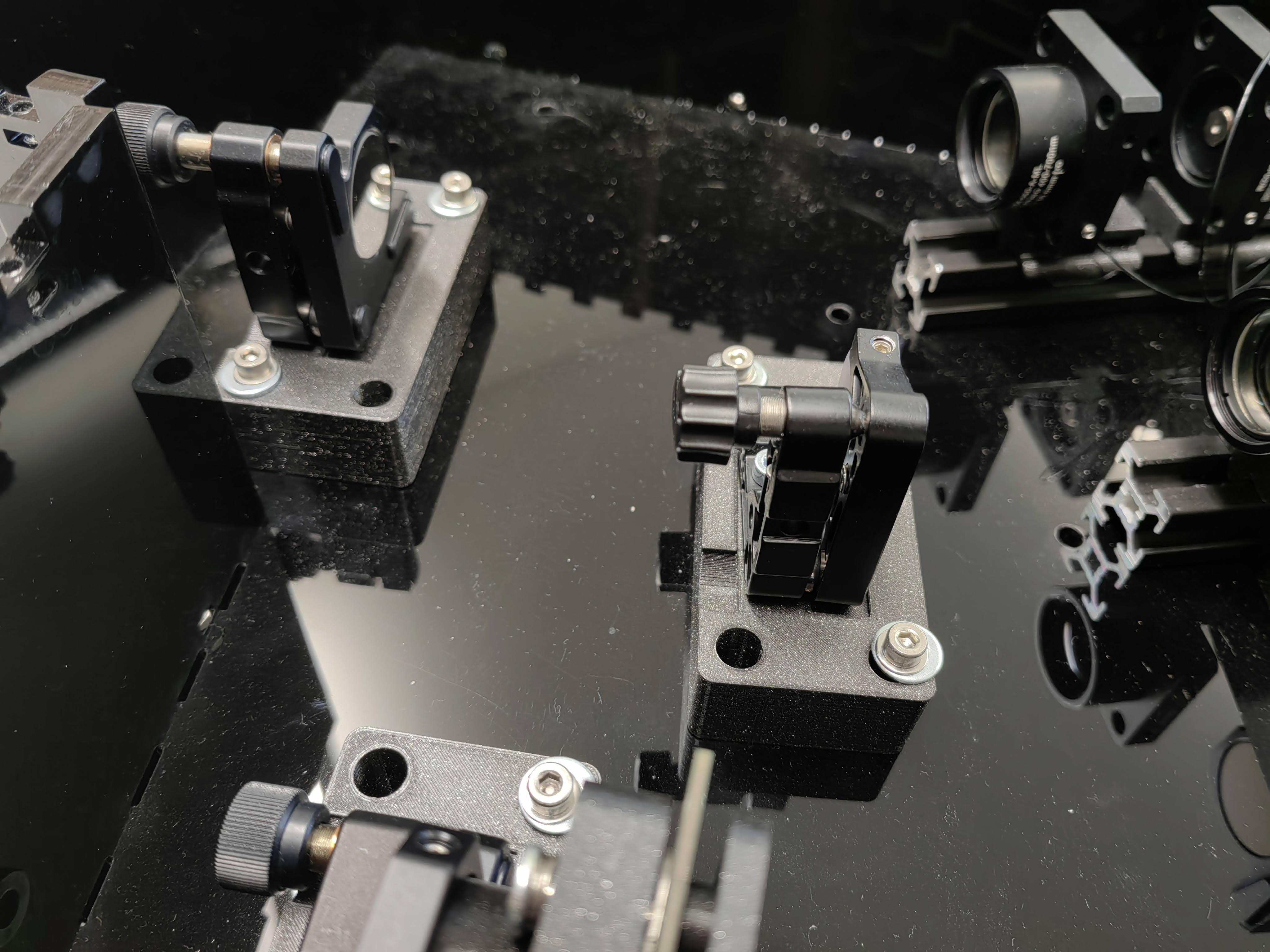
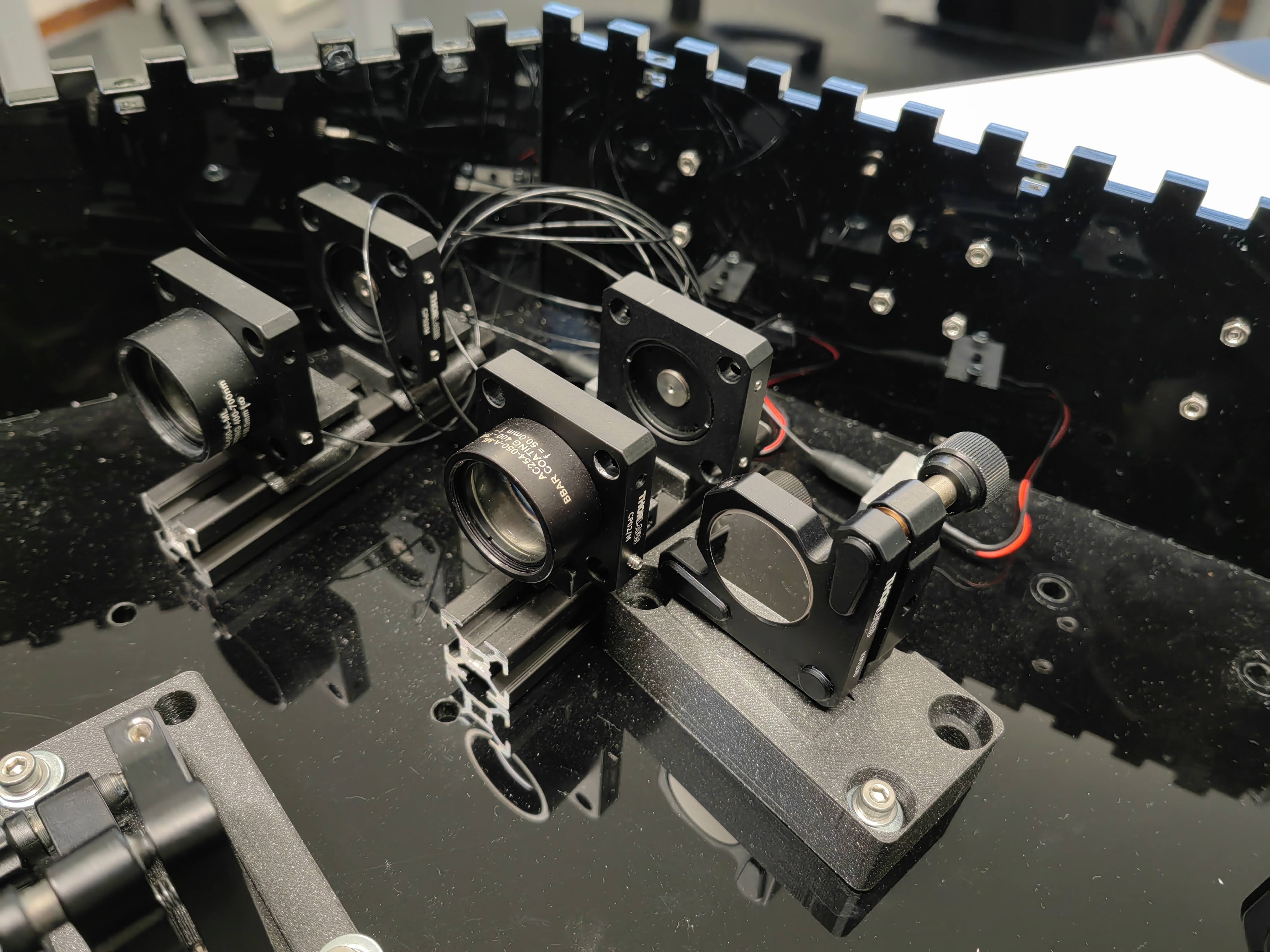
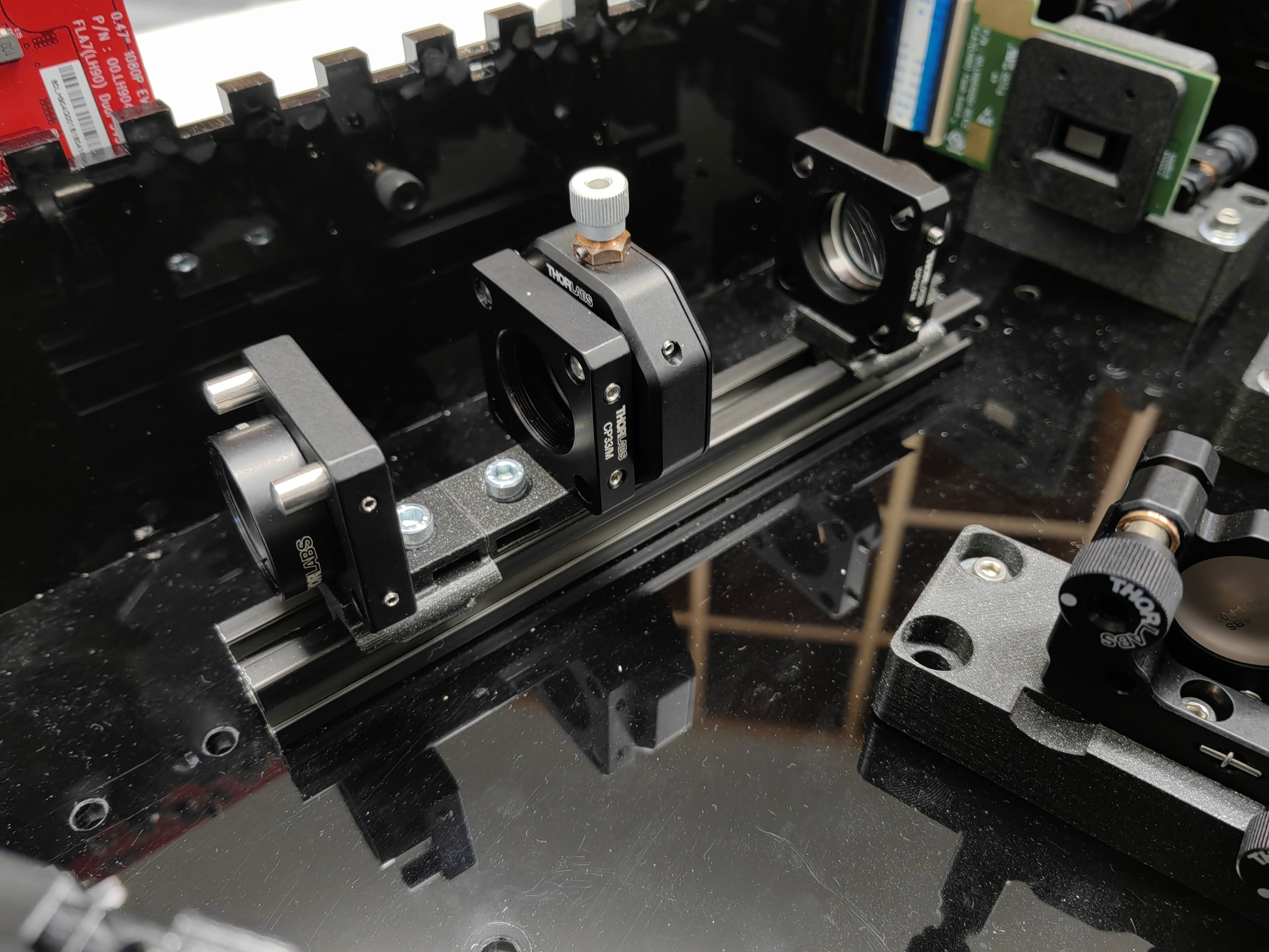
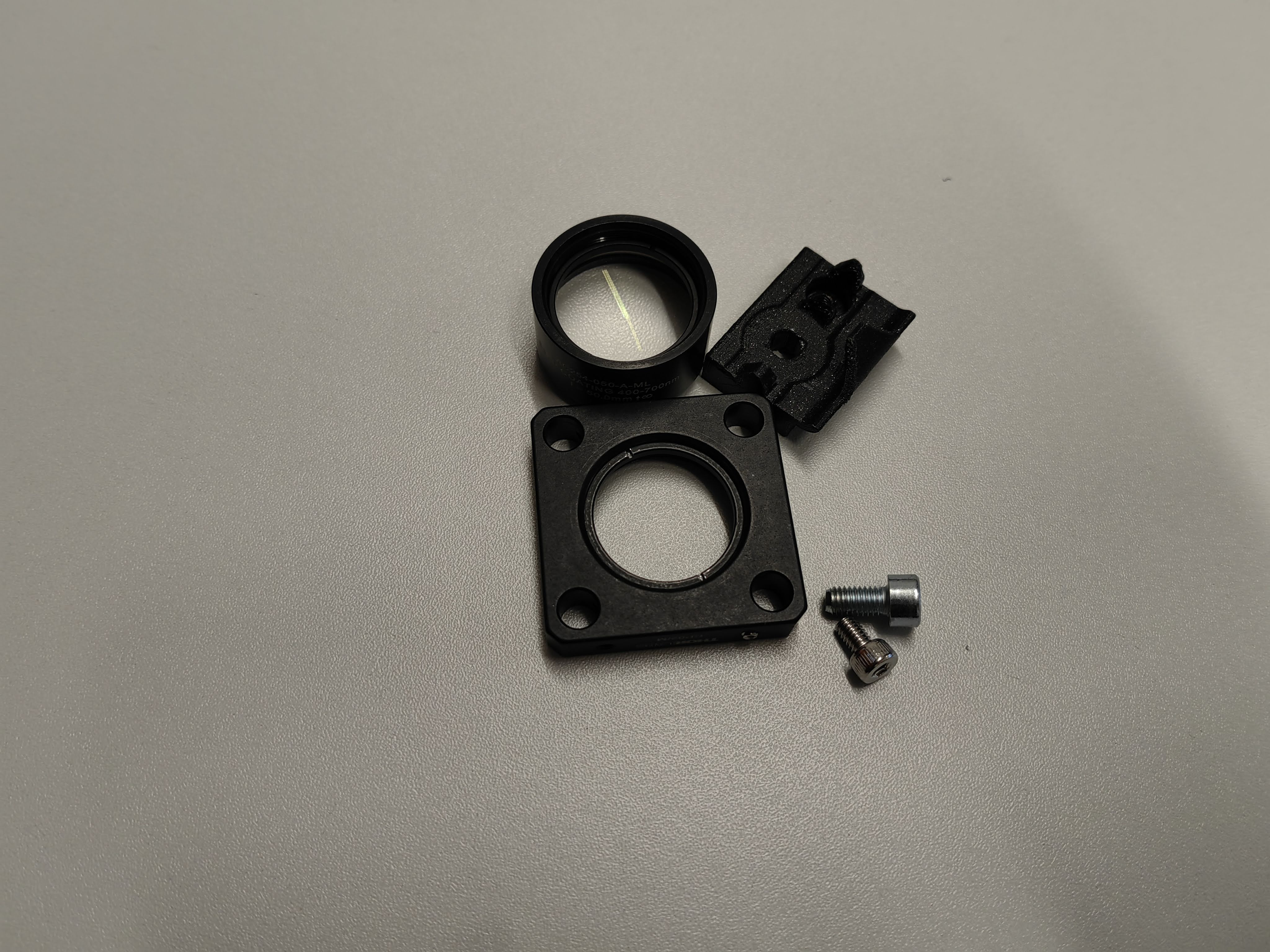
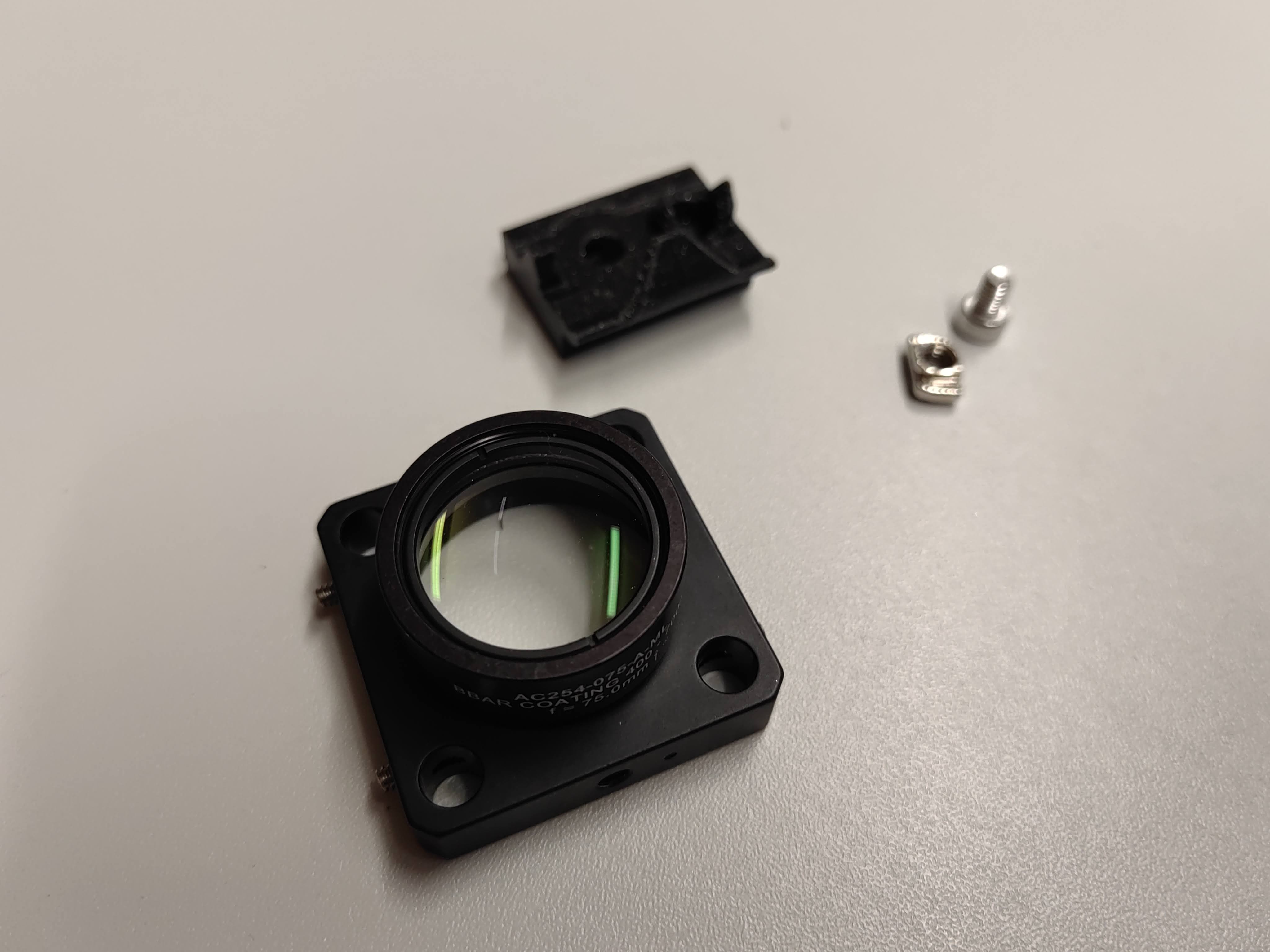
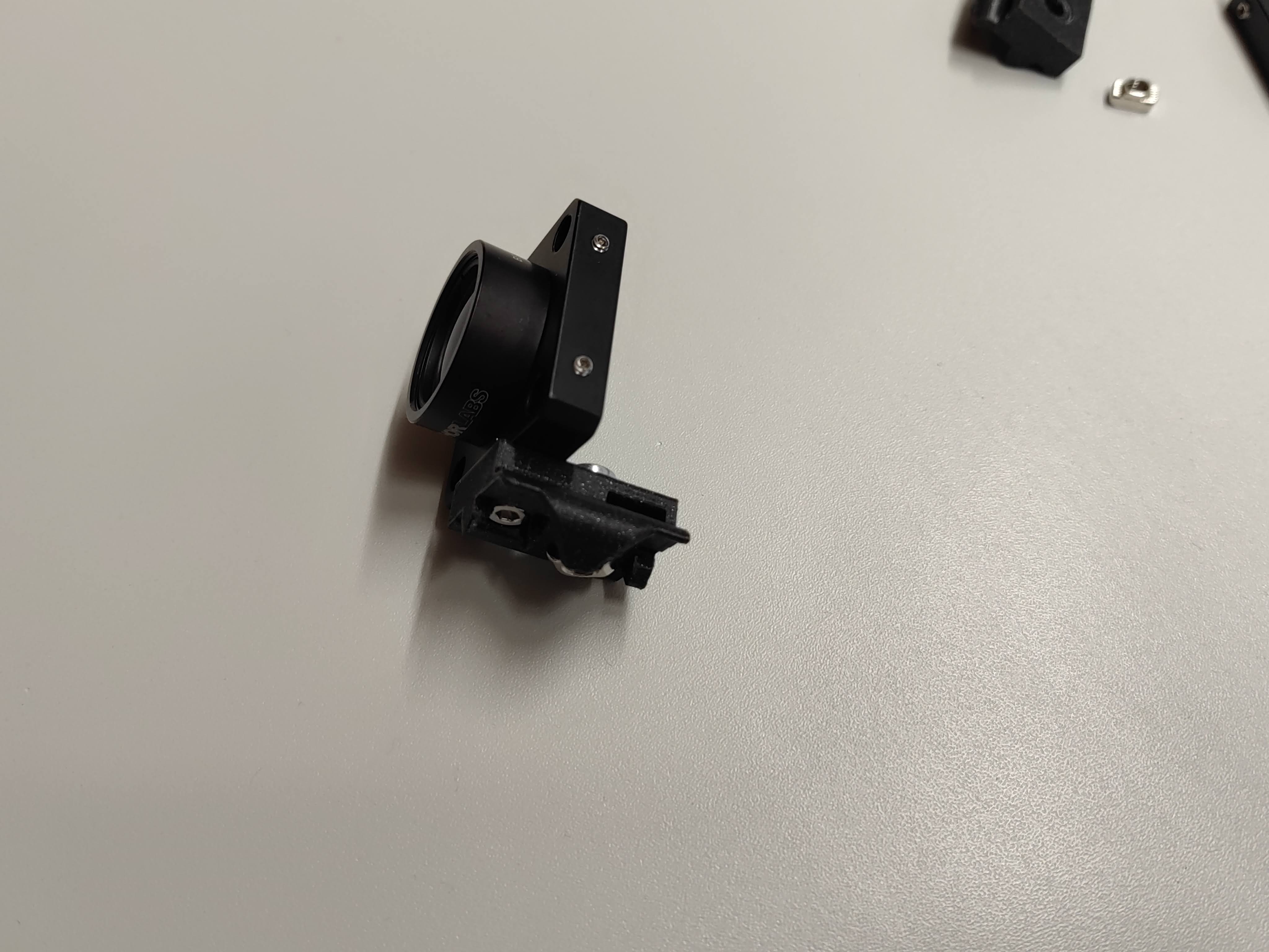
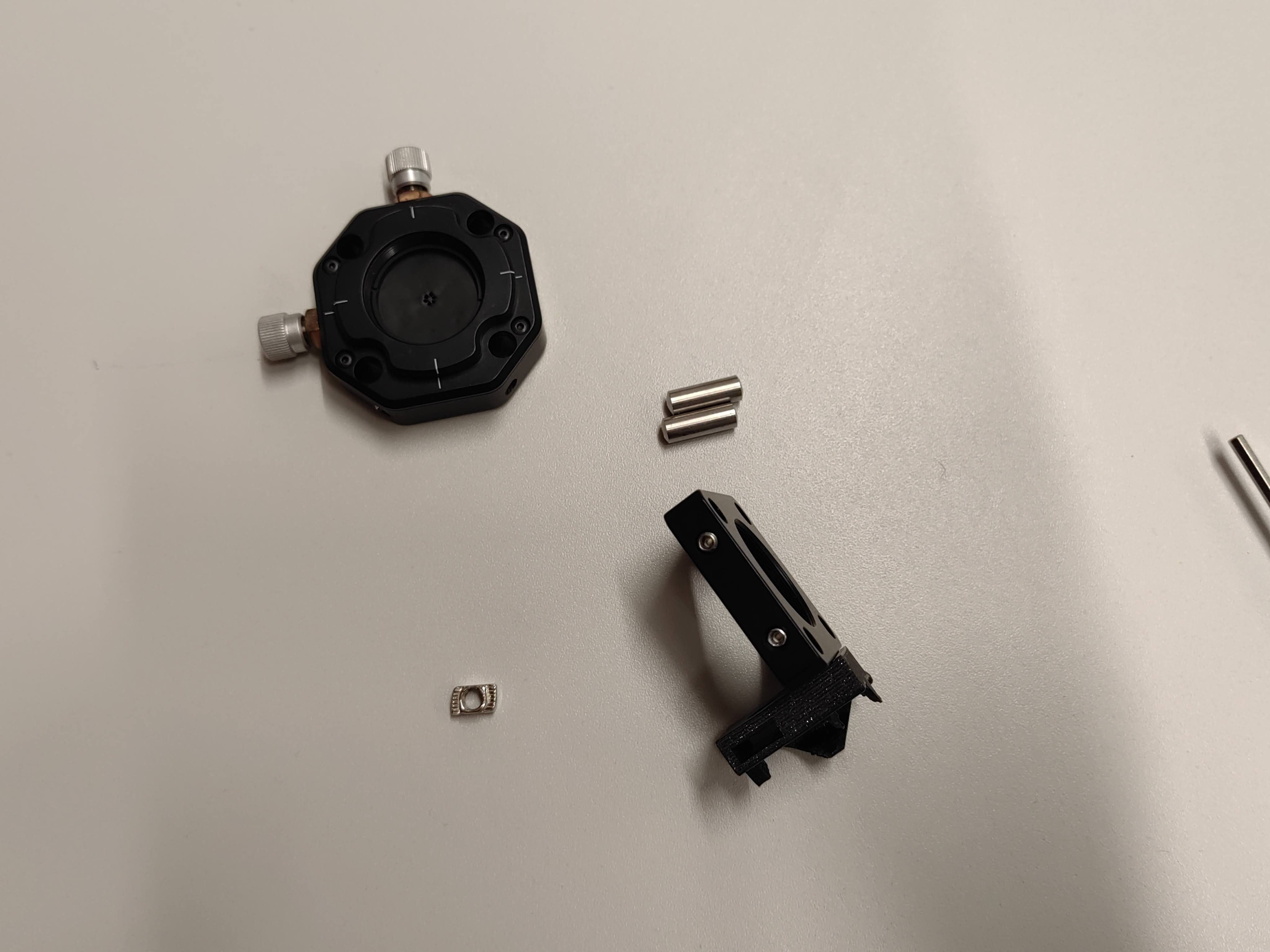
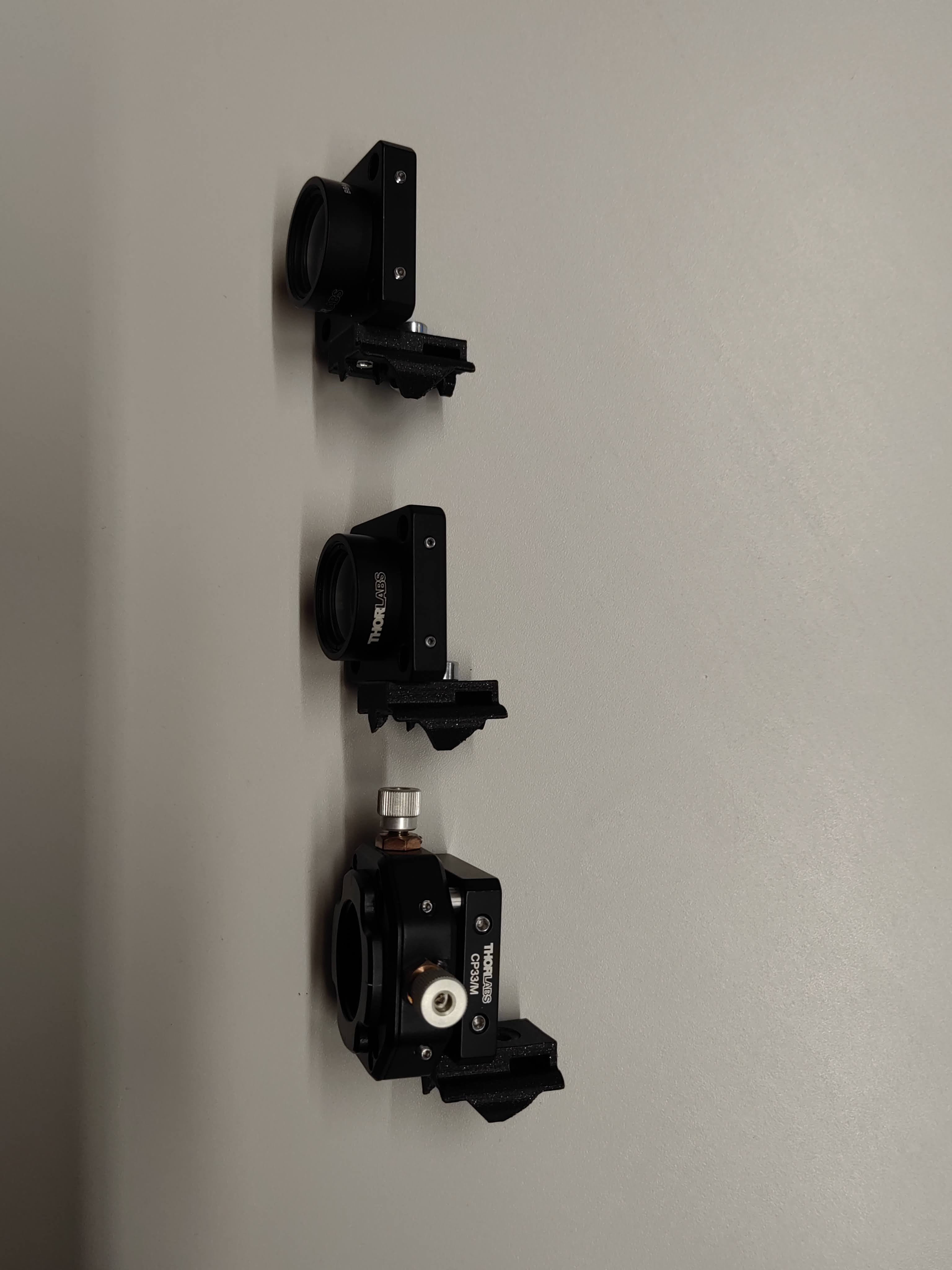
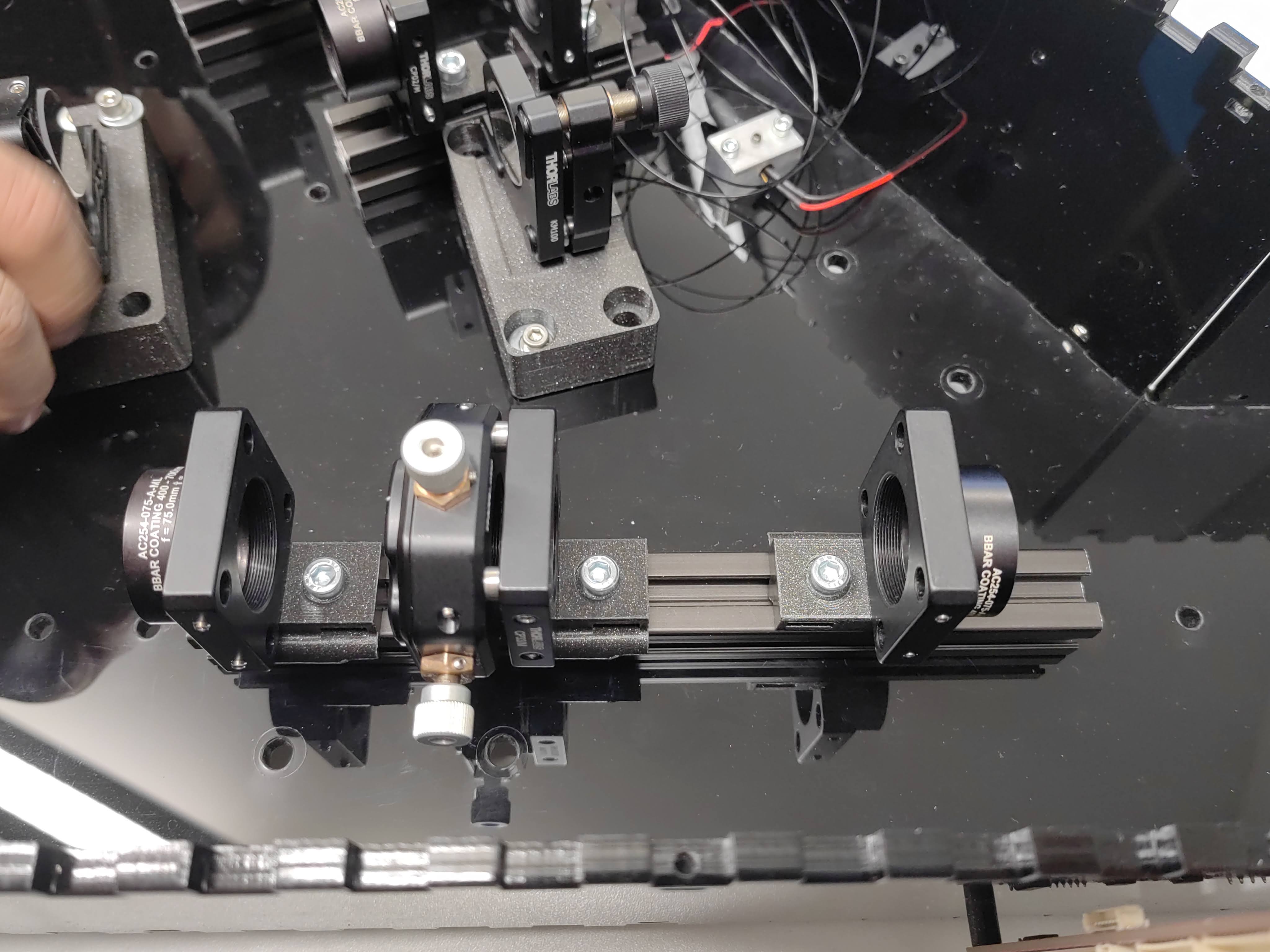
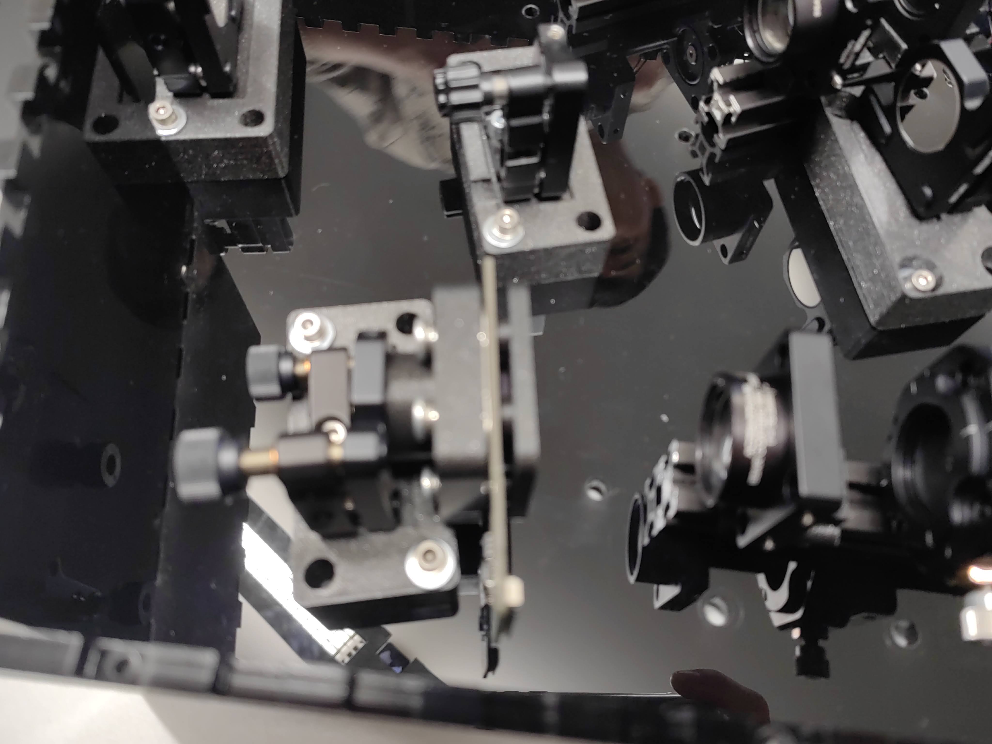
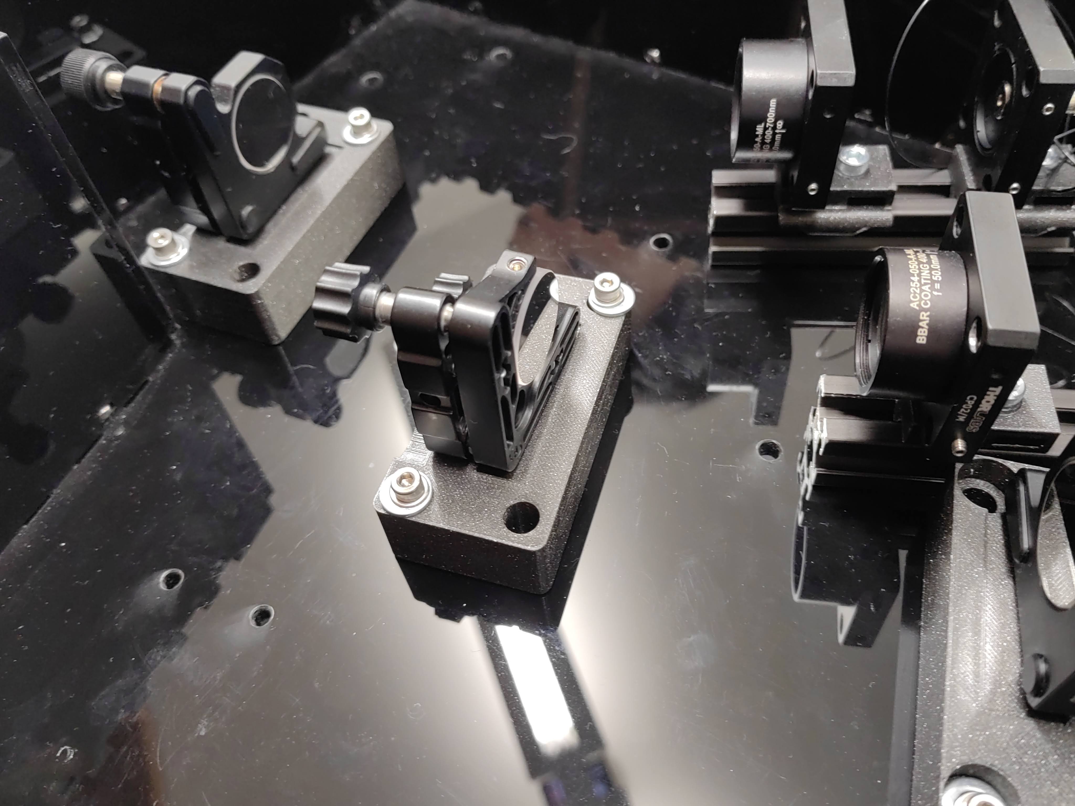
- Mounting optical component to optomechanics
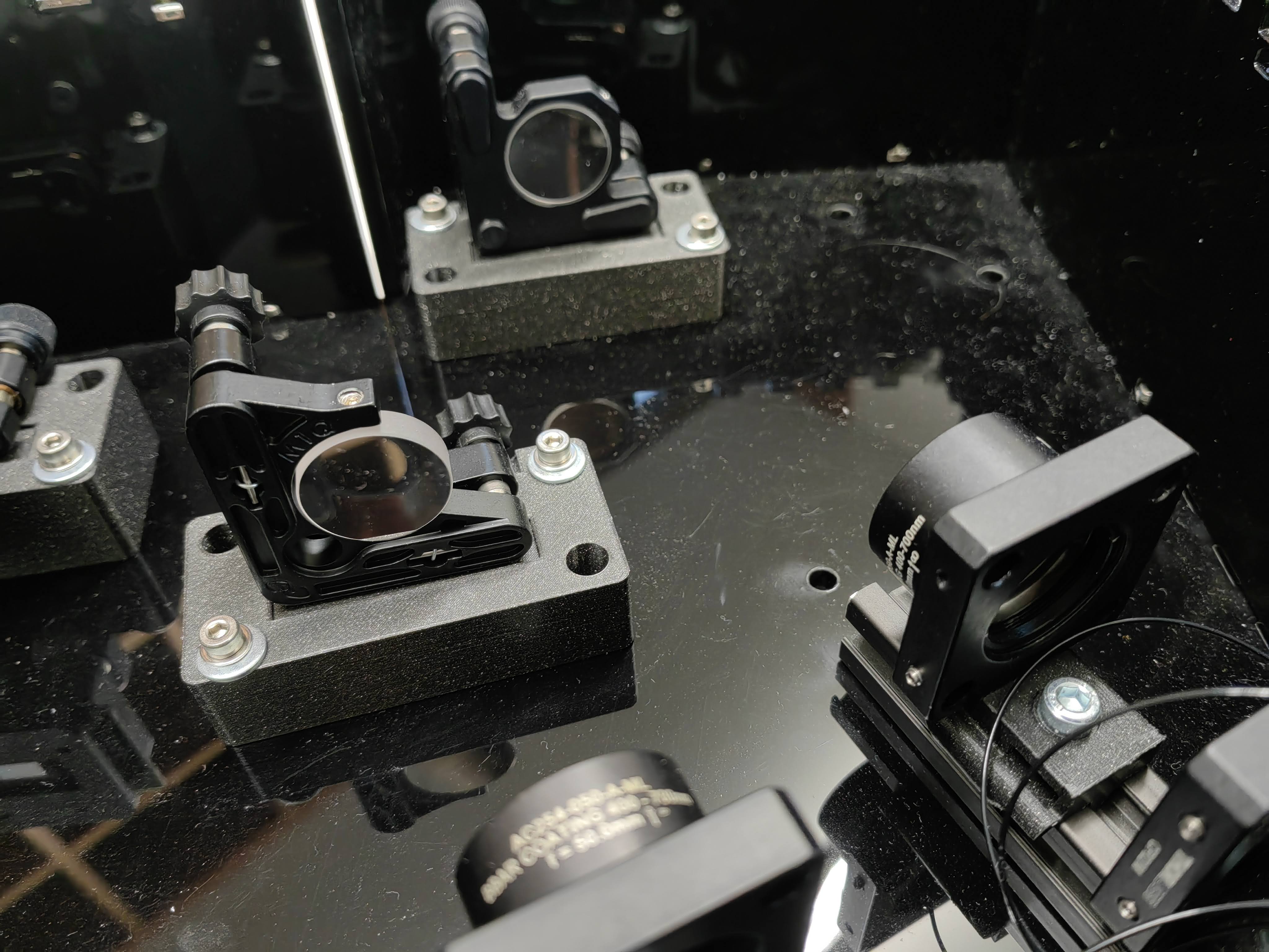
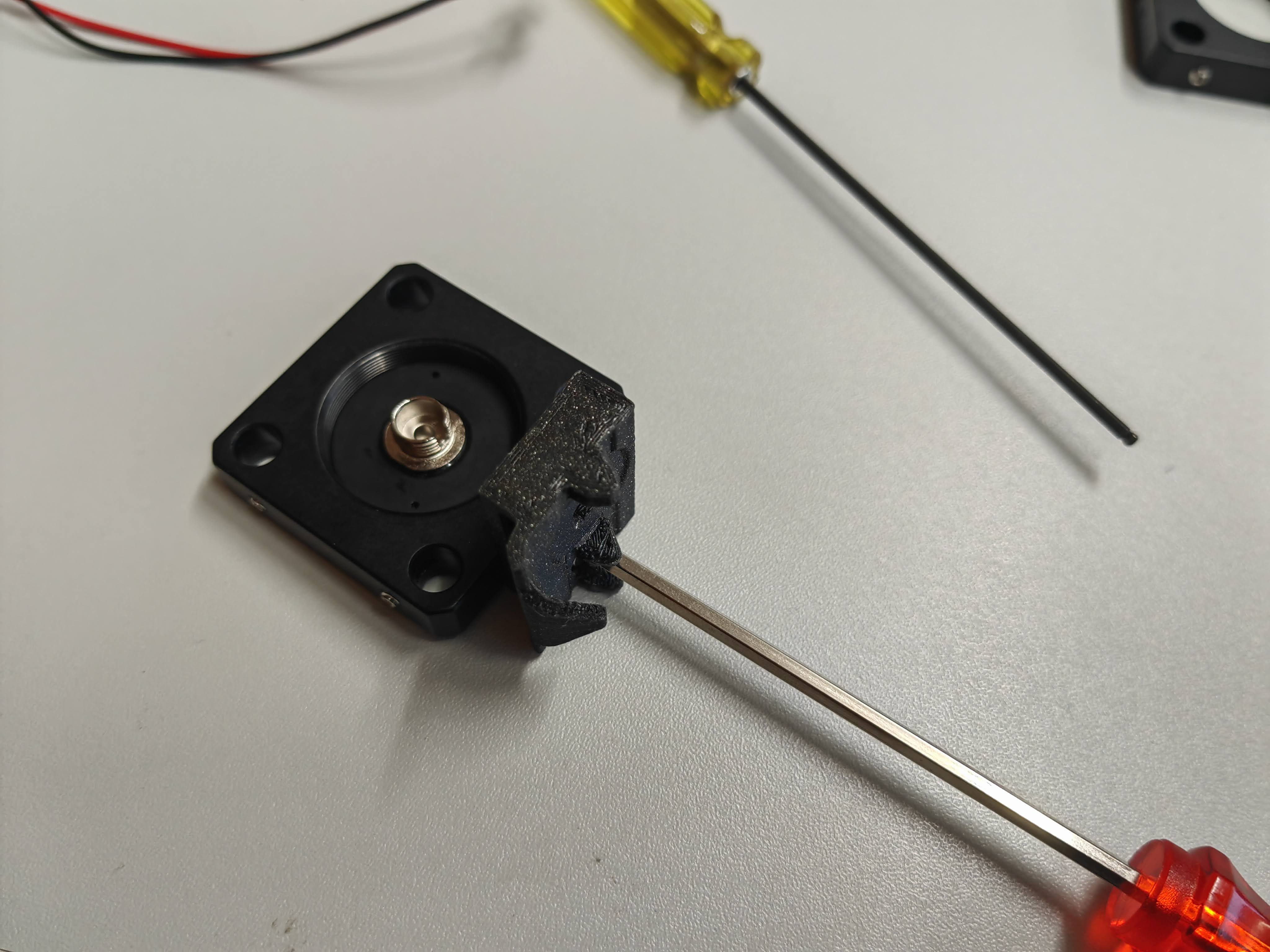
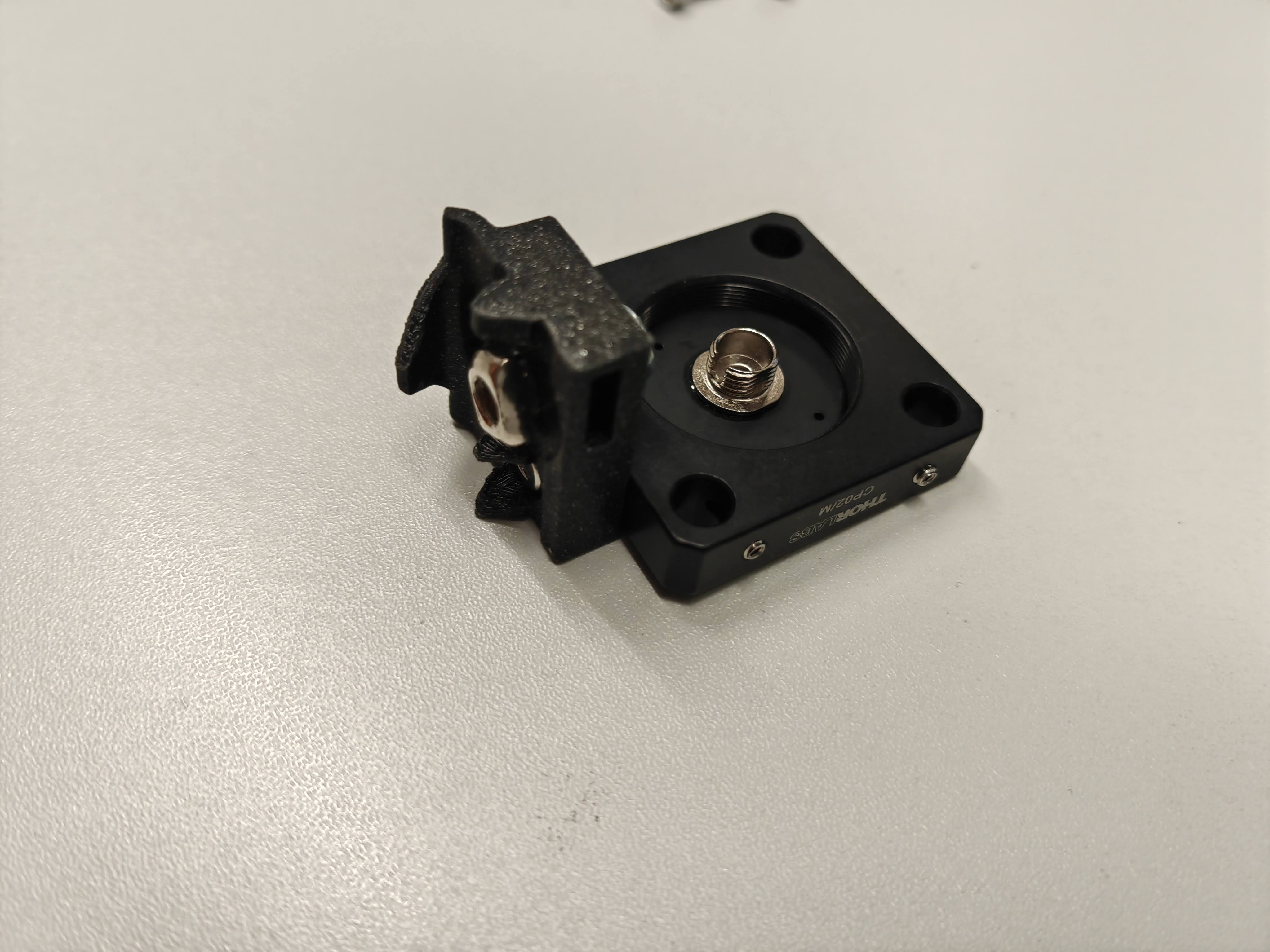
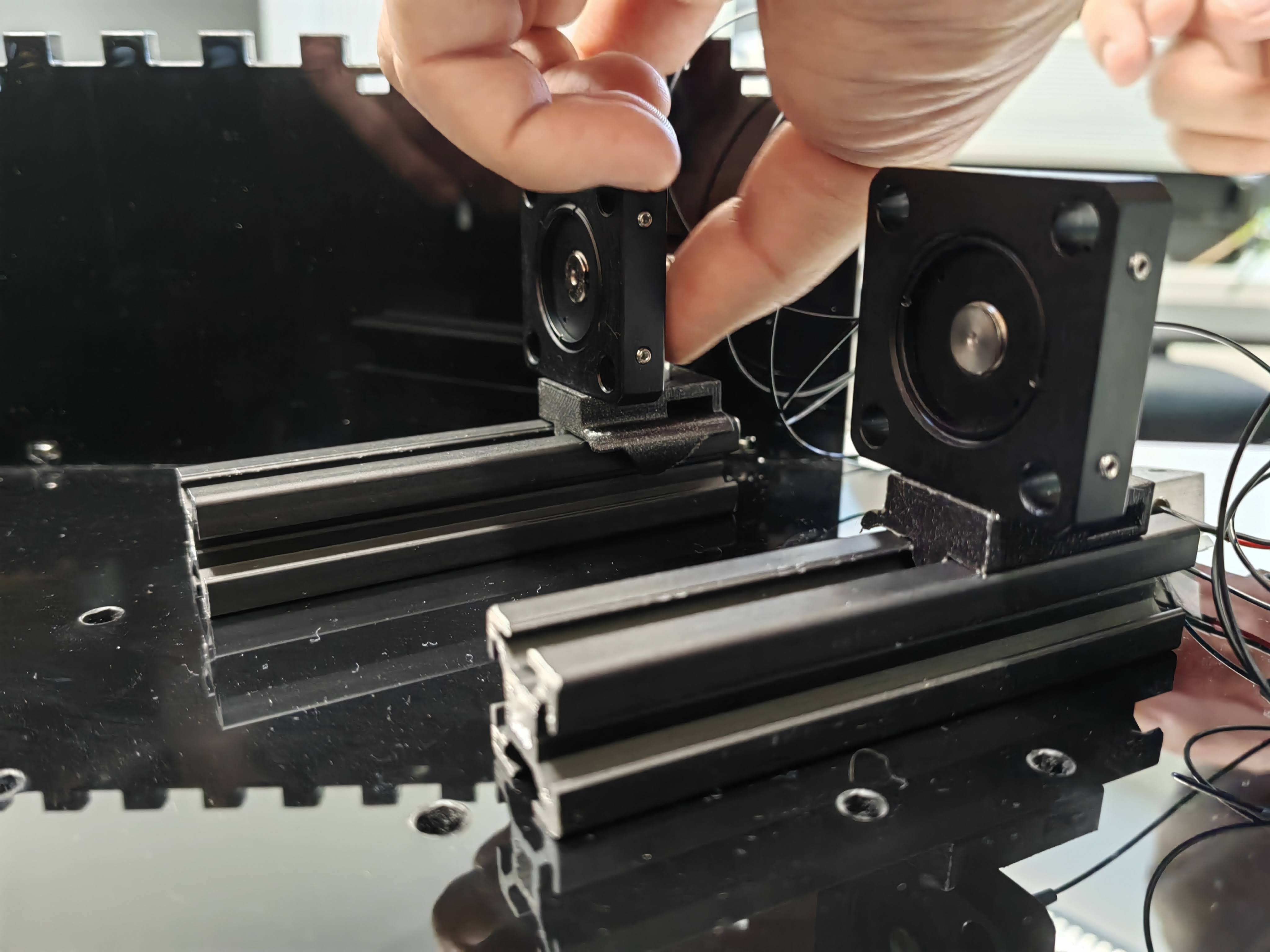
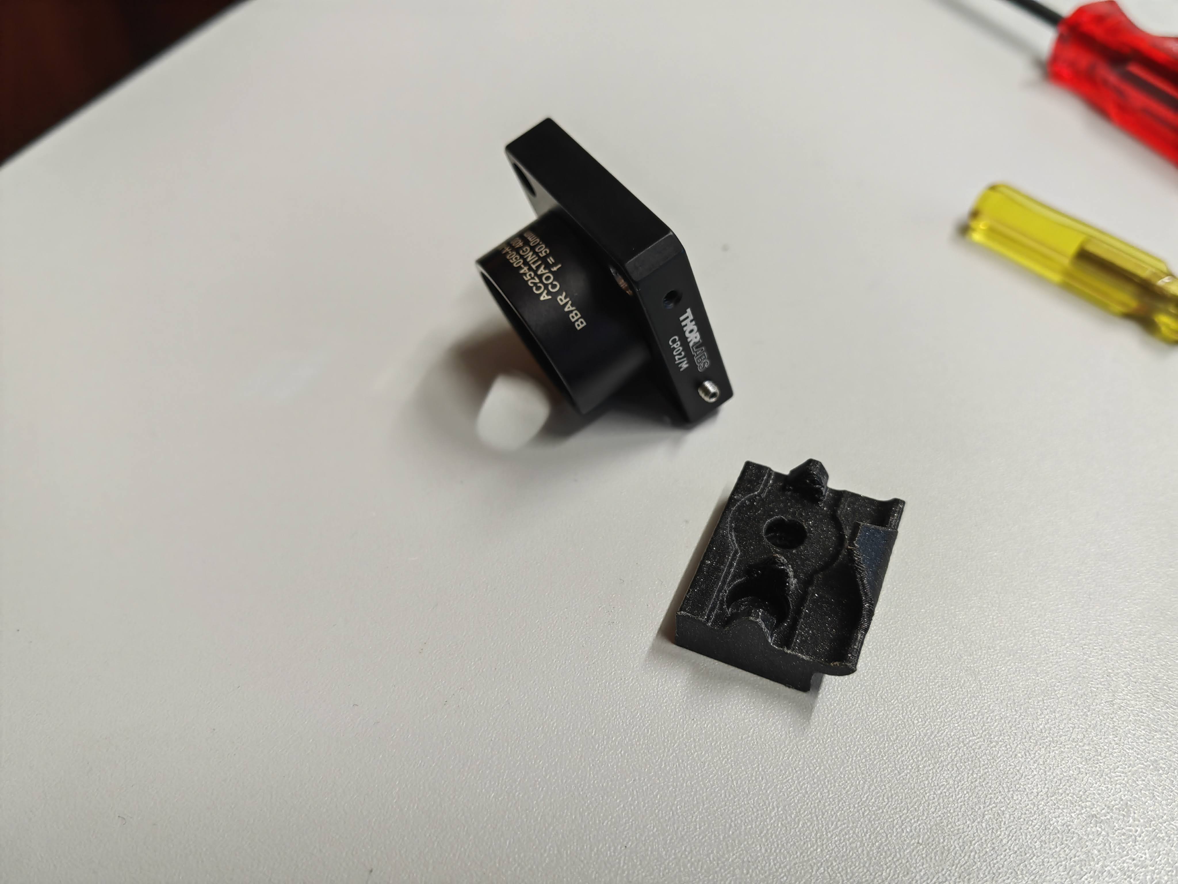
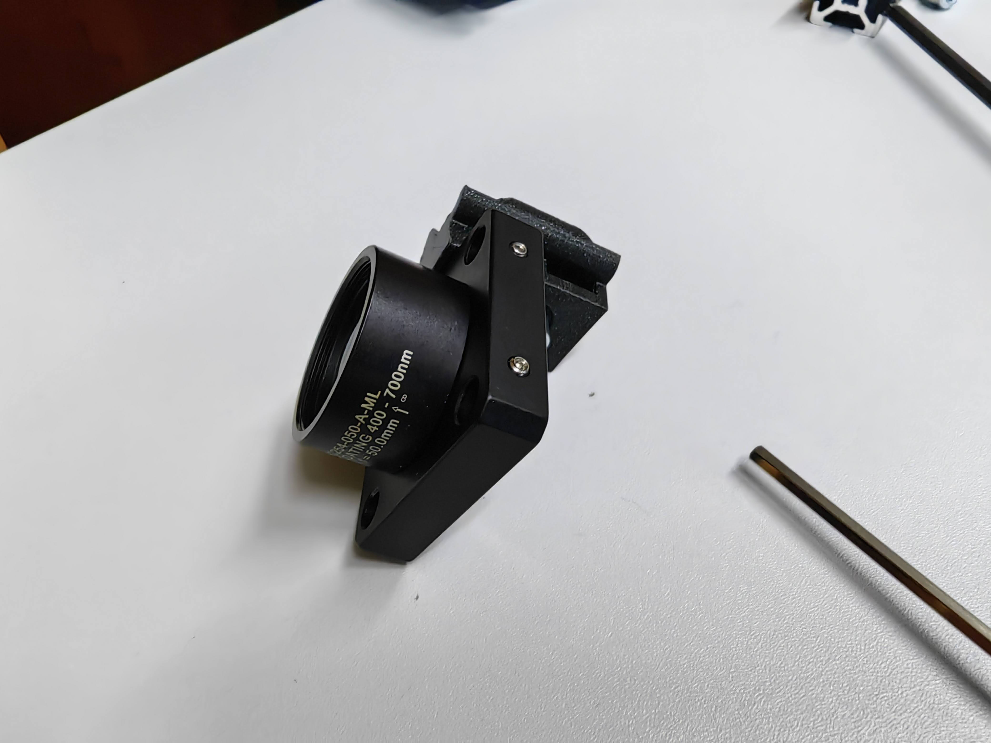
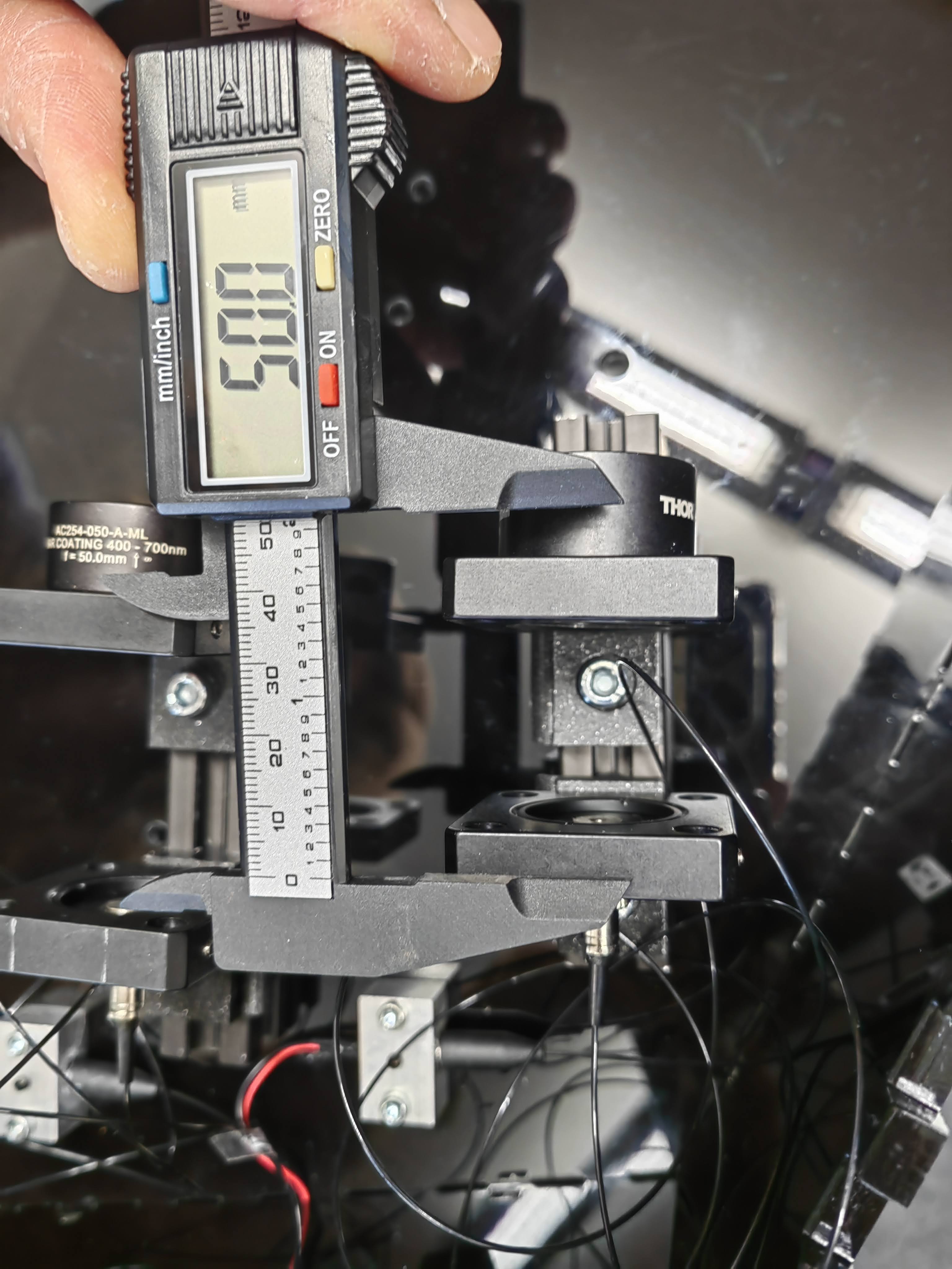
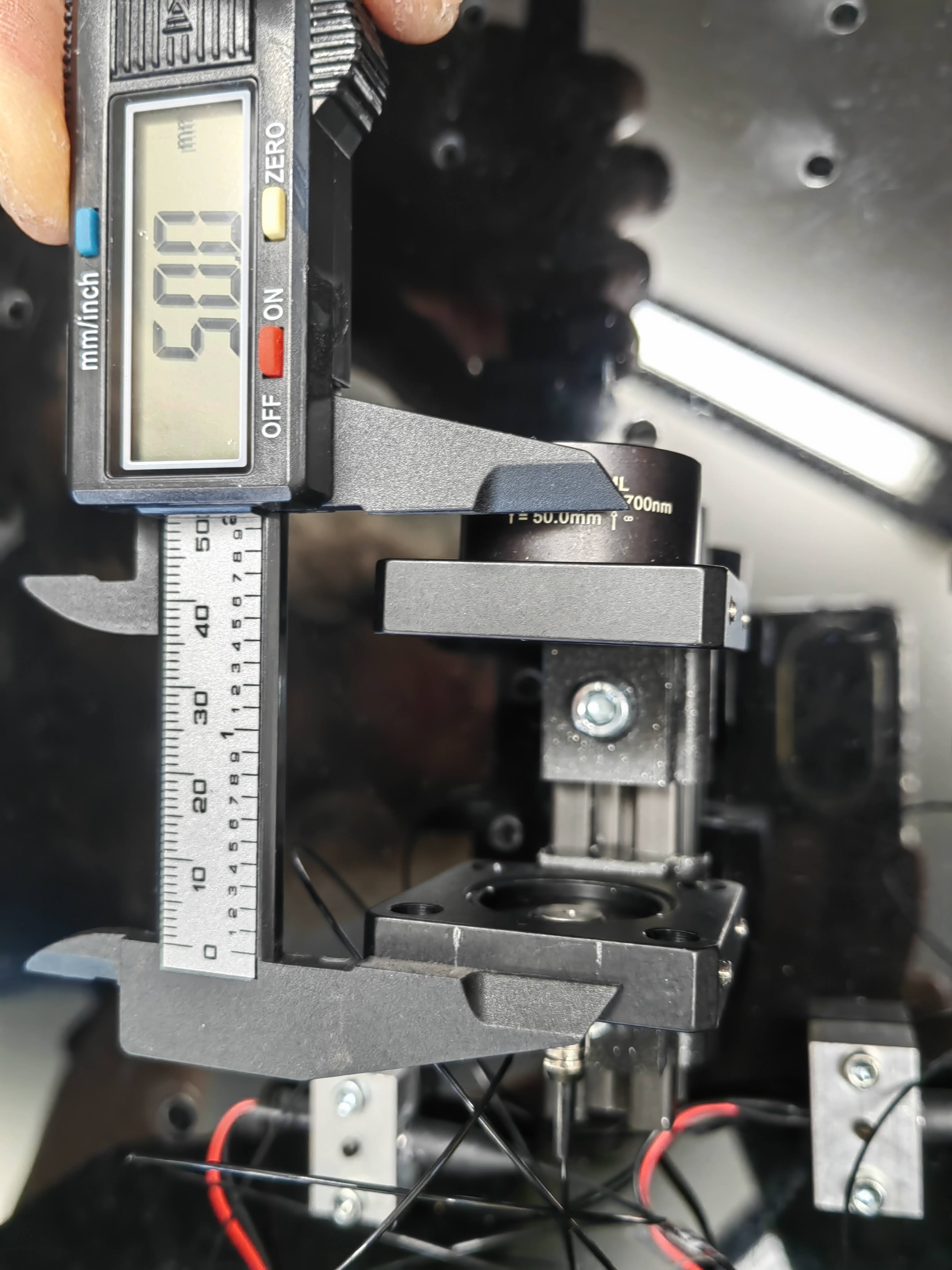
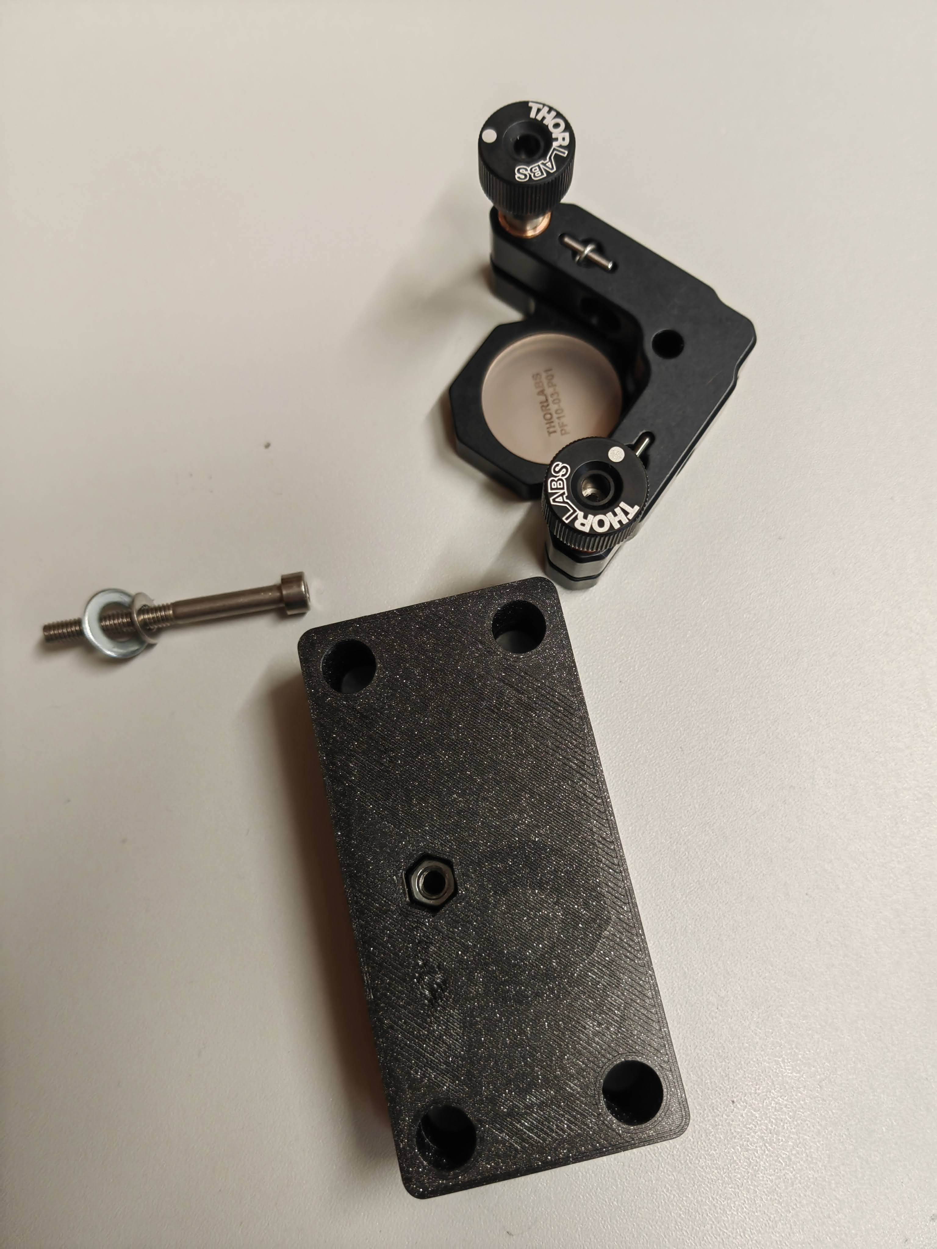
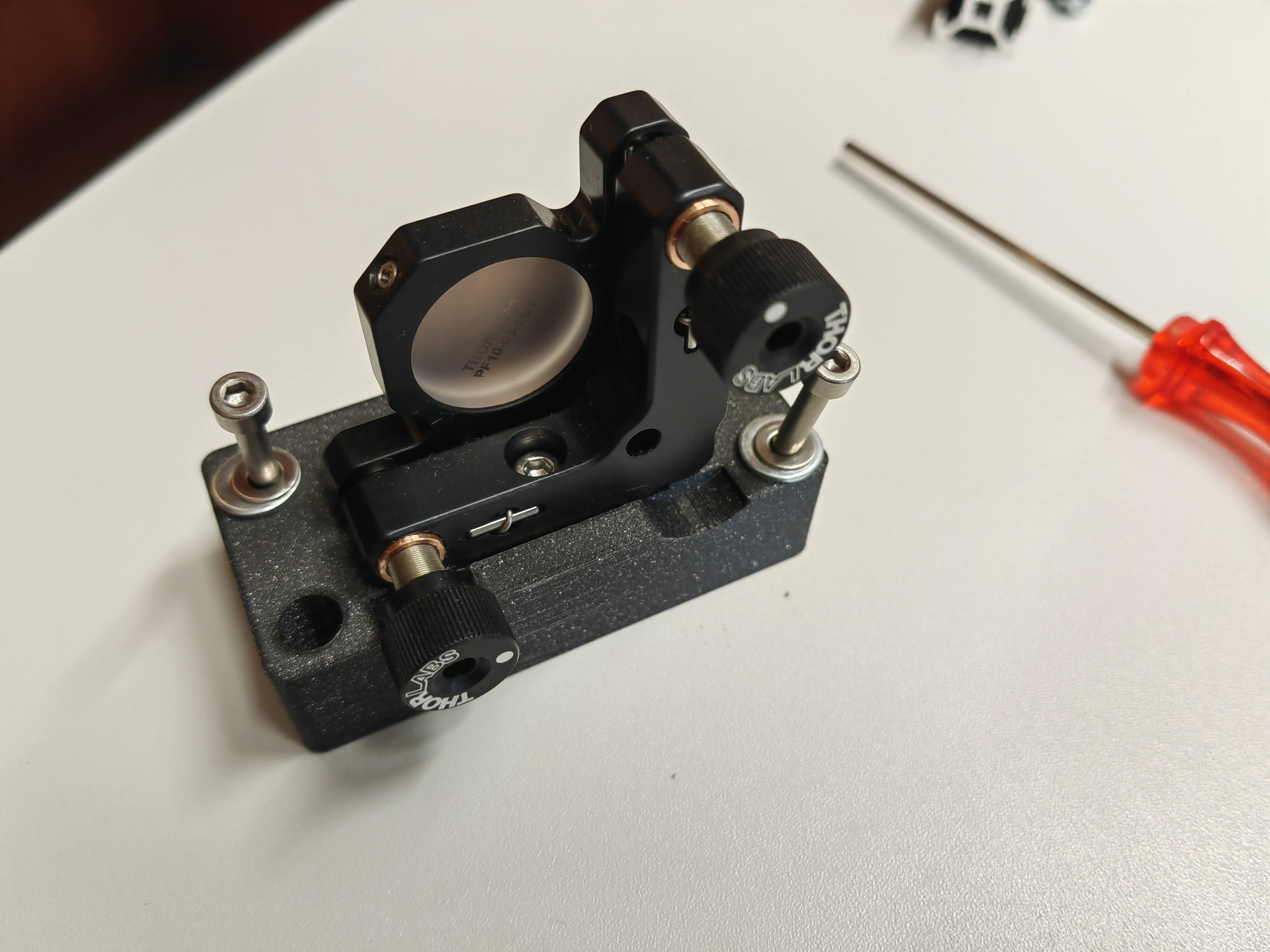
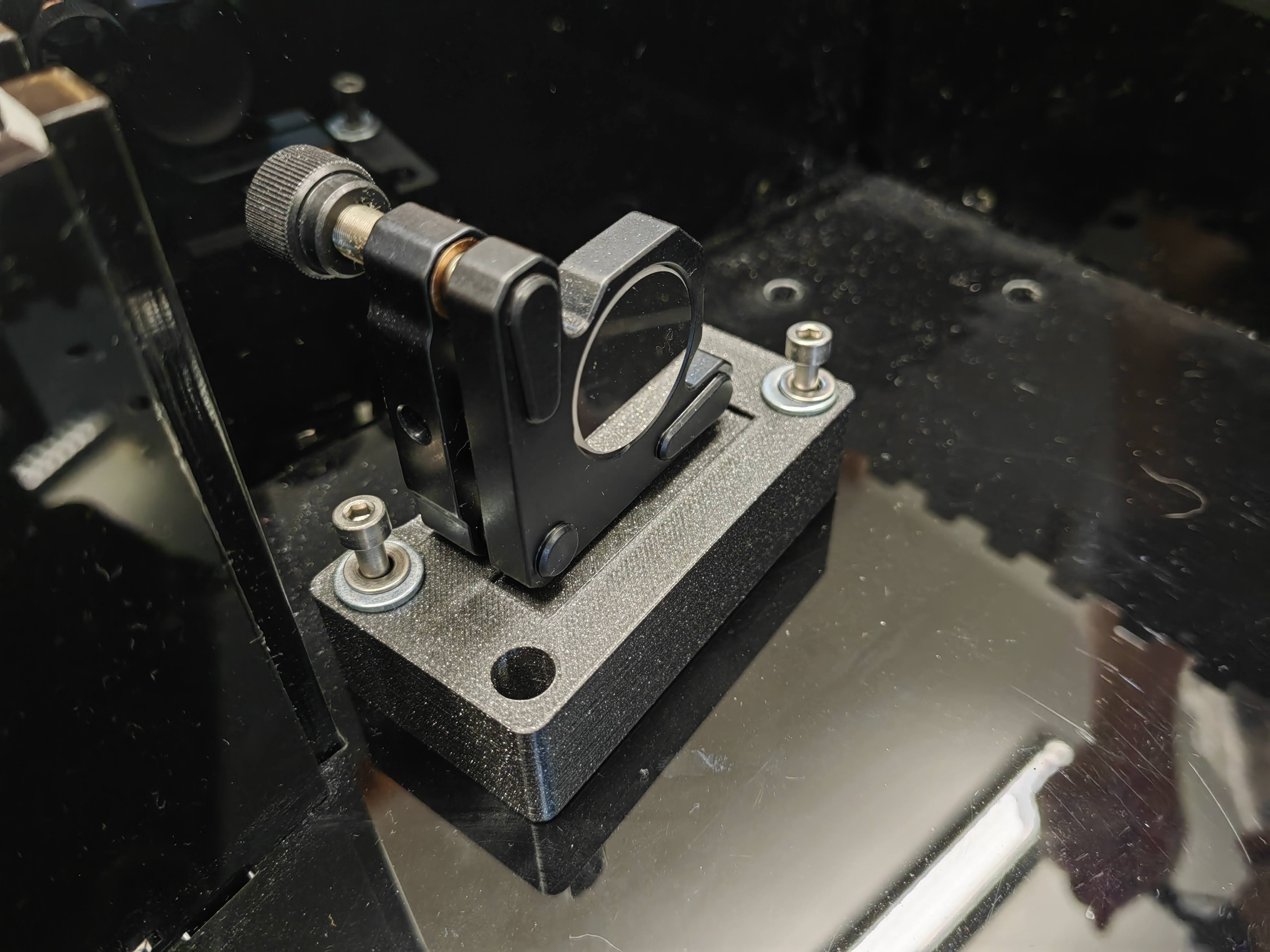
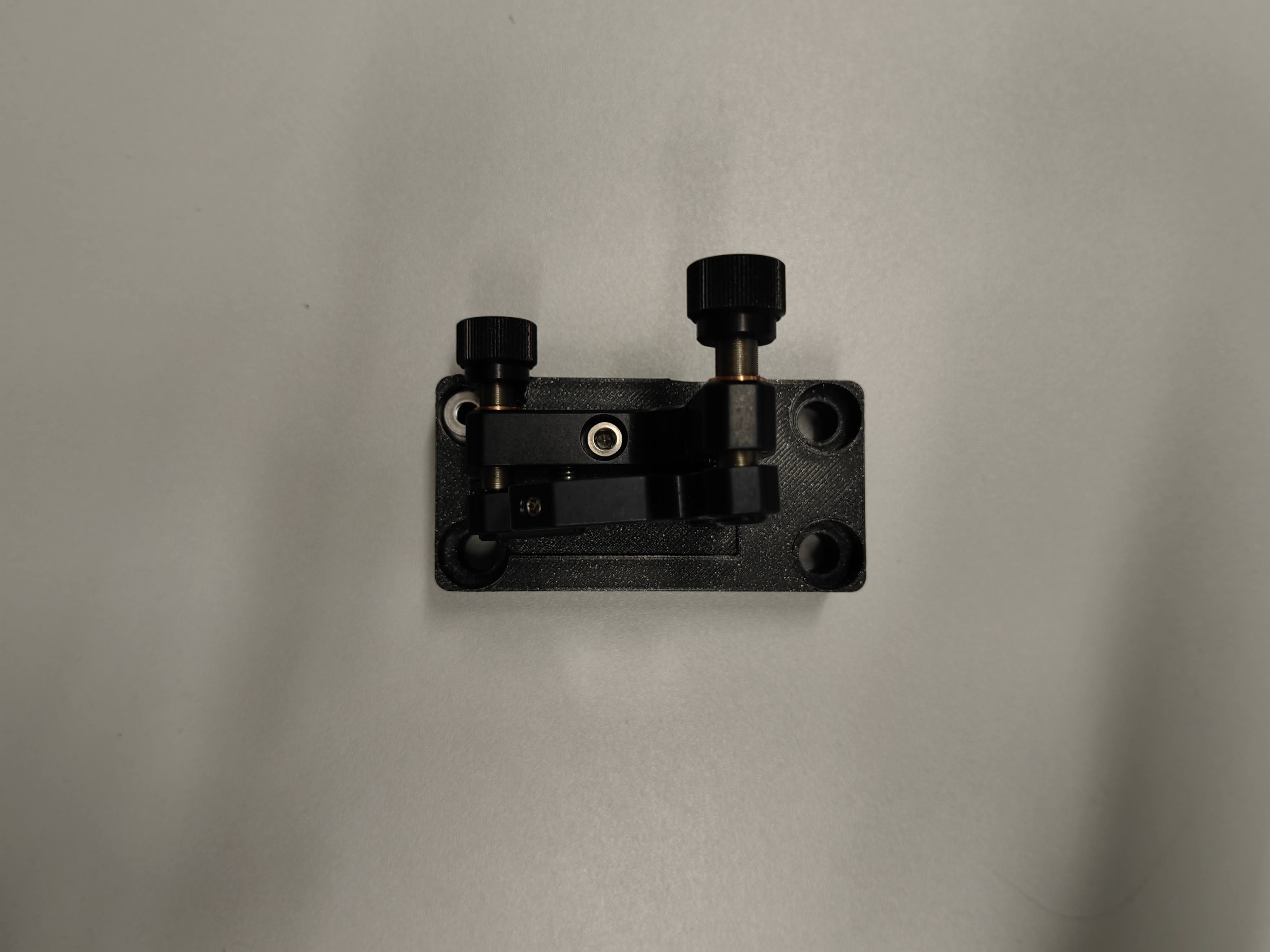
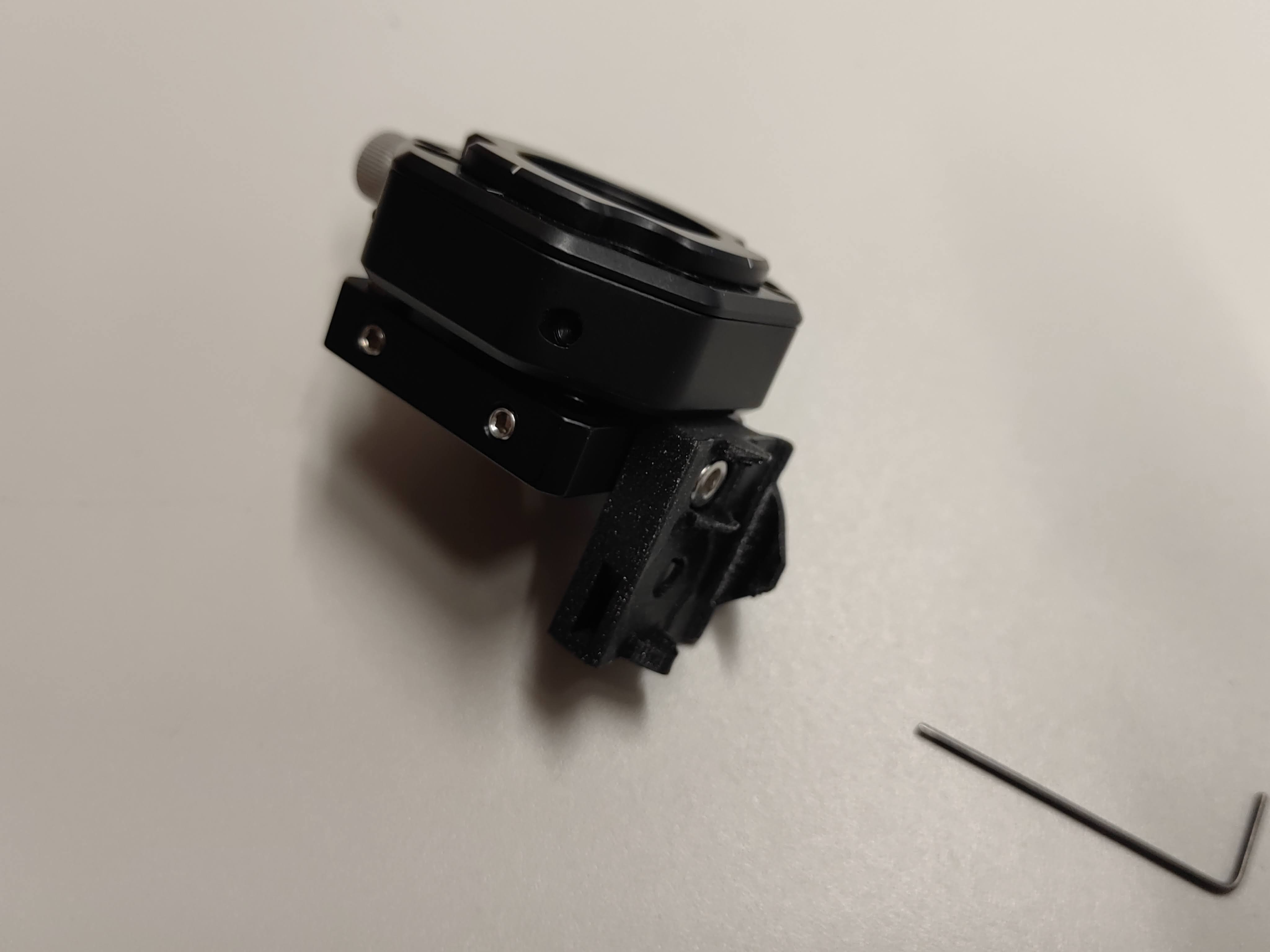
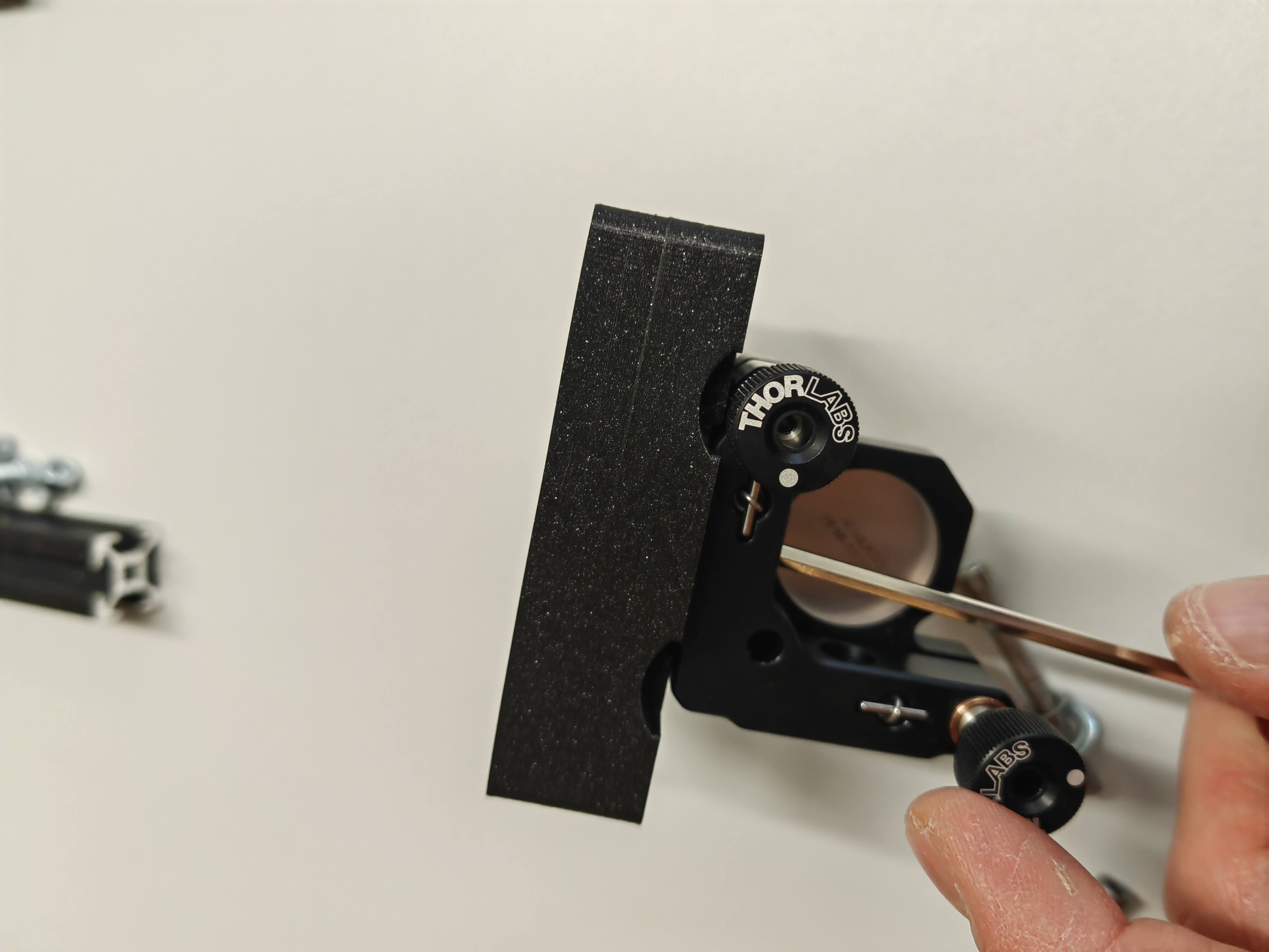
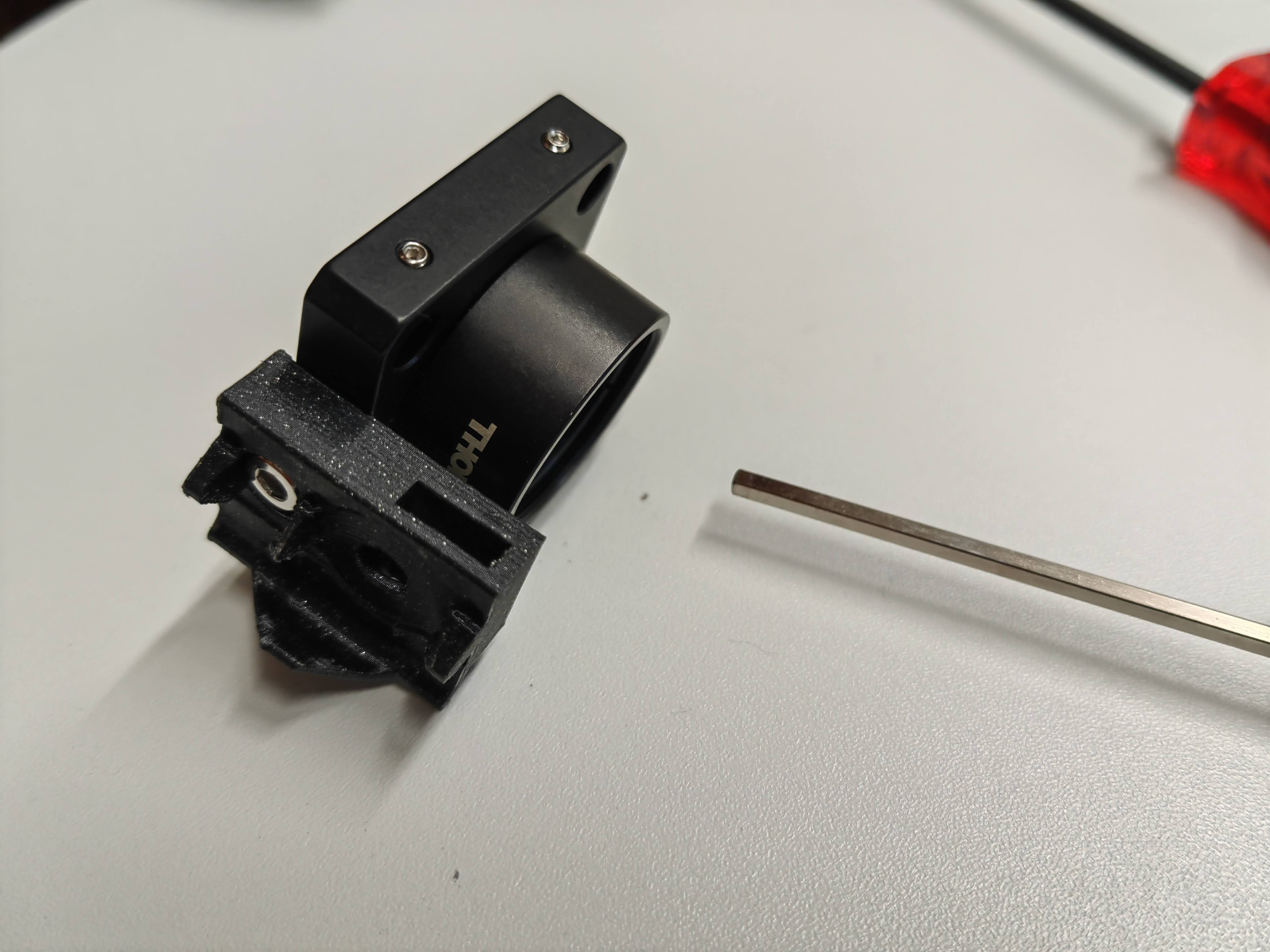
The optical elements are all direct connected to optomechanics. It makes sense to fix the optical parts directly in optomechanics. Mirrors are connected to the kinematic mirror mount, put them in the correct position and lock it using the screw on the edge.
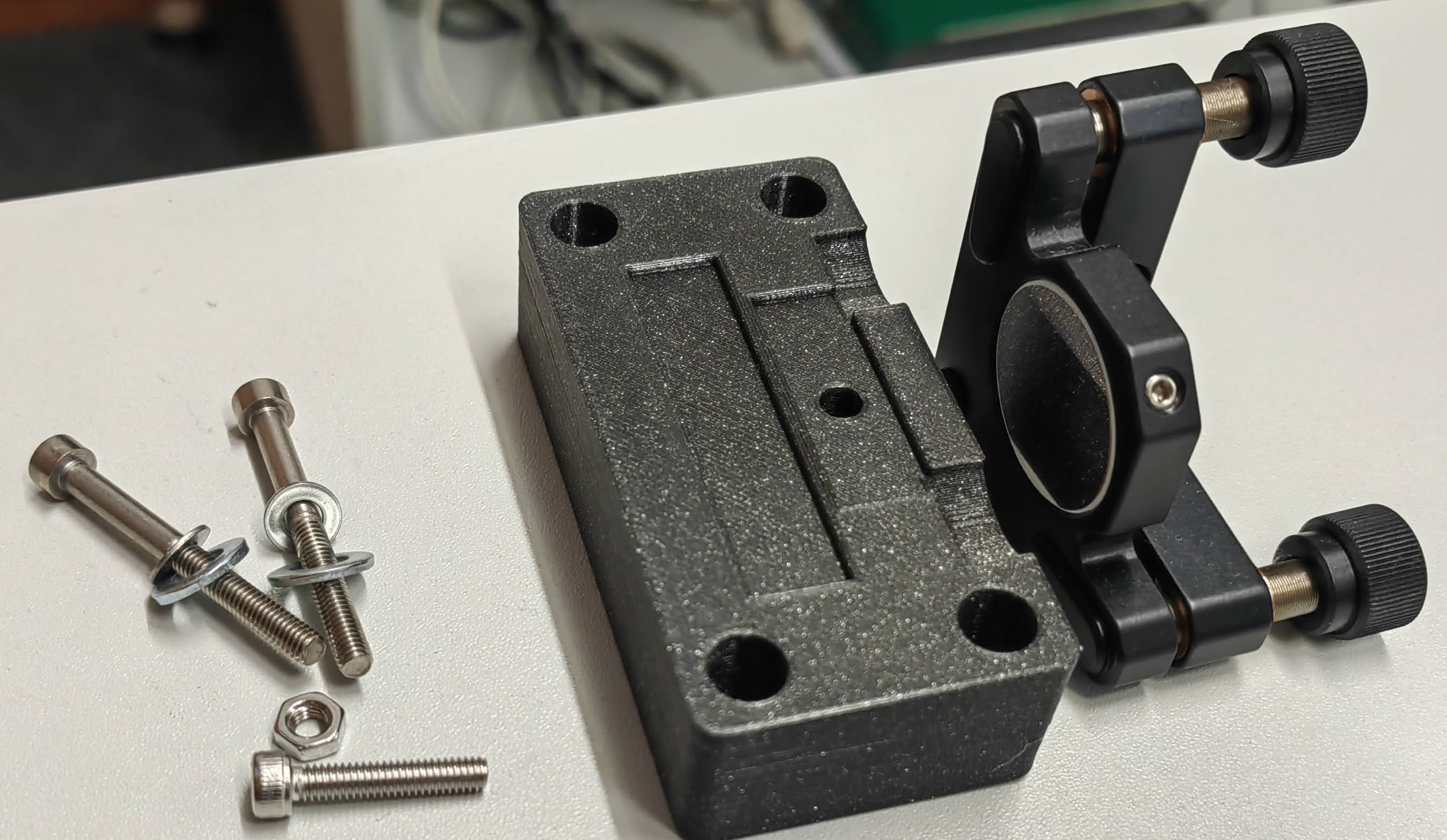
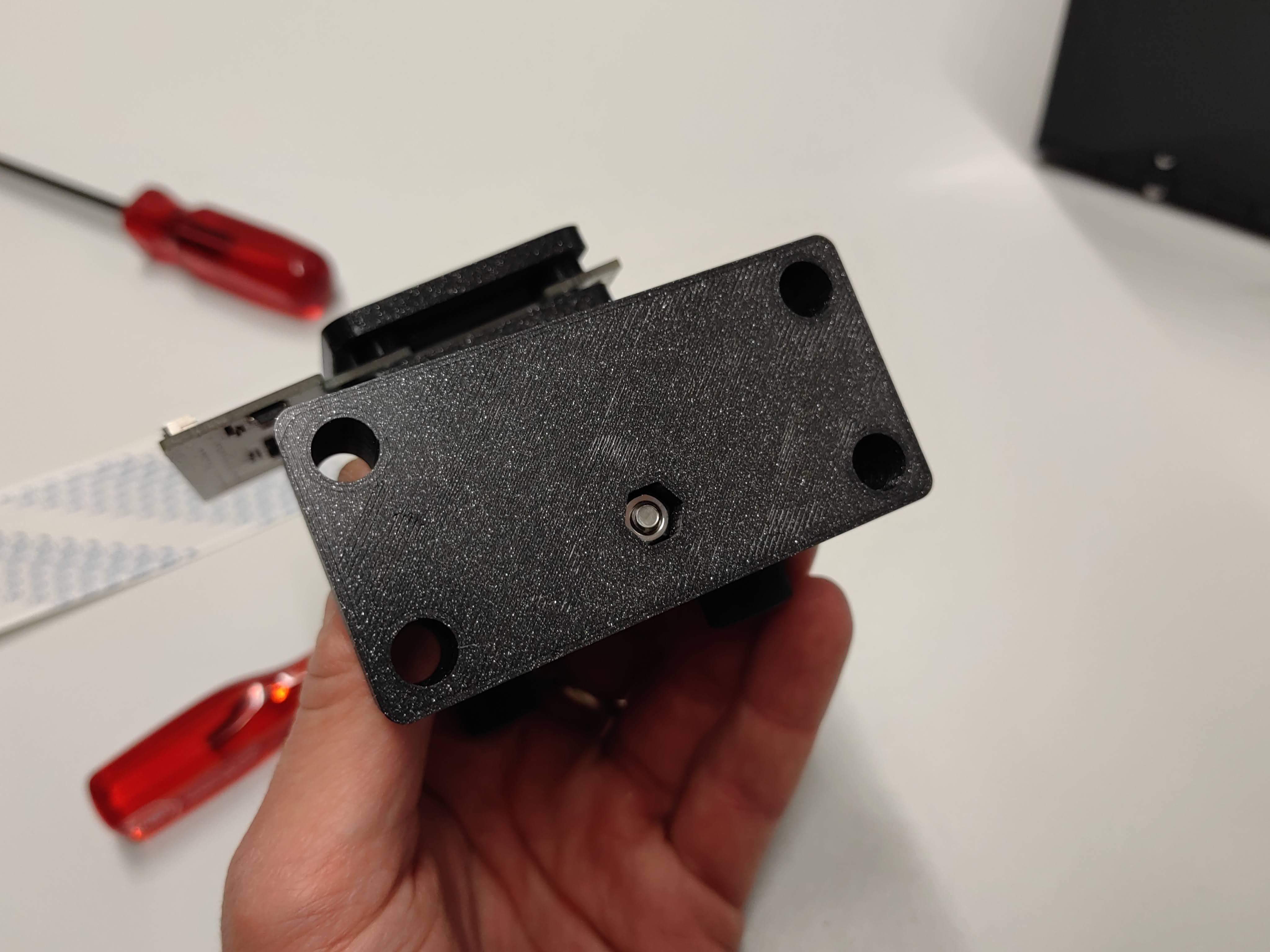
Then the kinematic mounts are fixed tightly on the mount plates with long M4 screws and nuts.
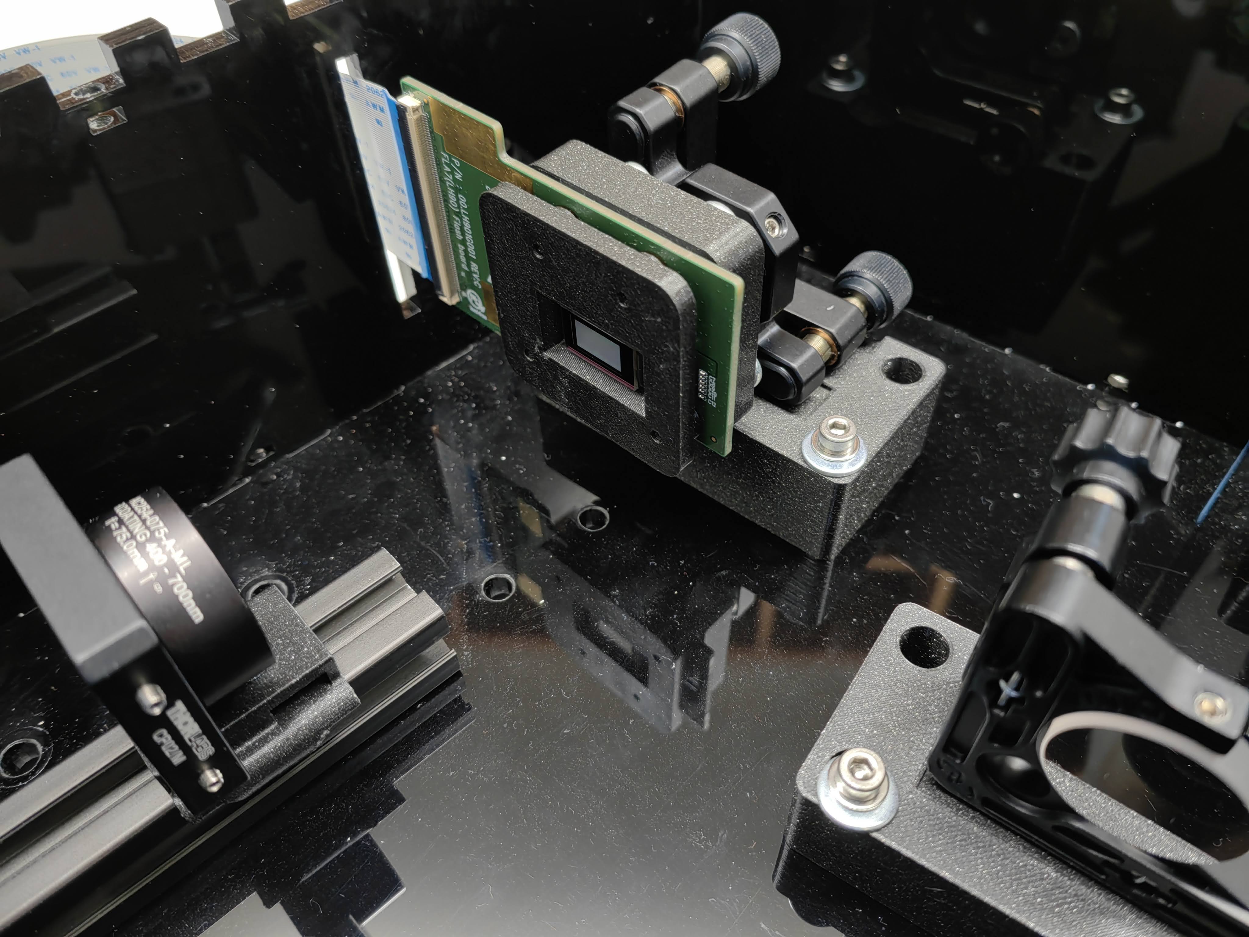
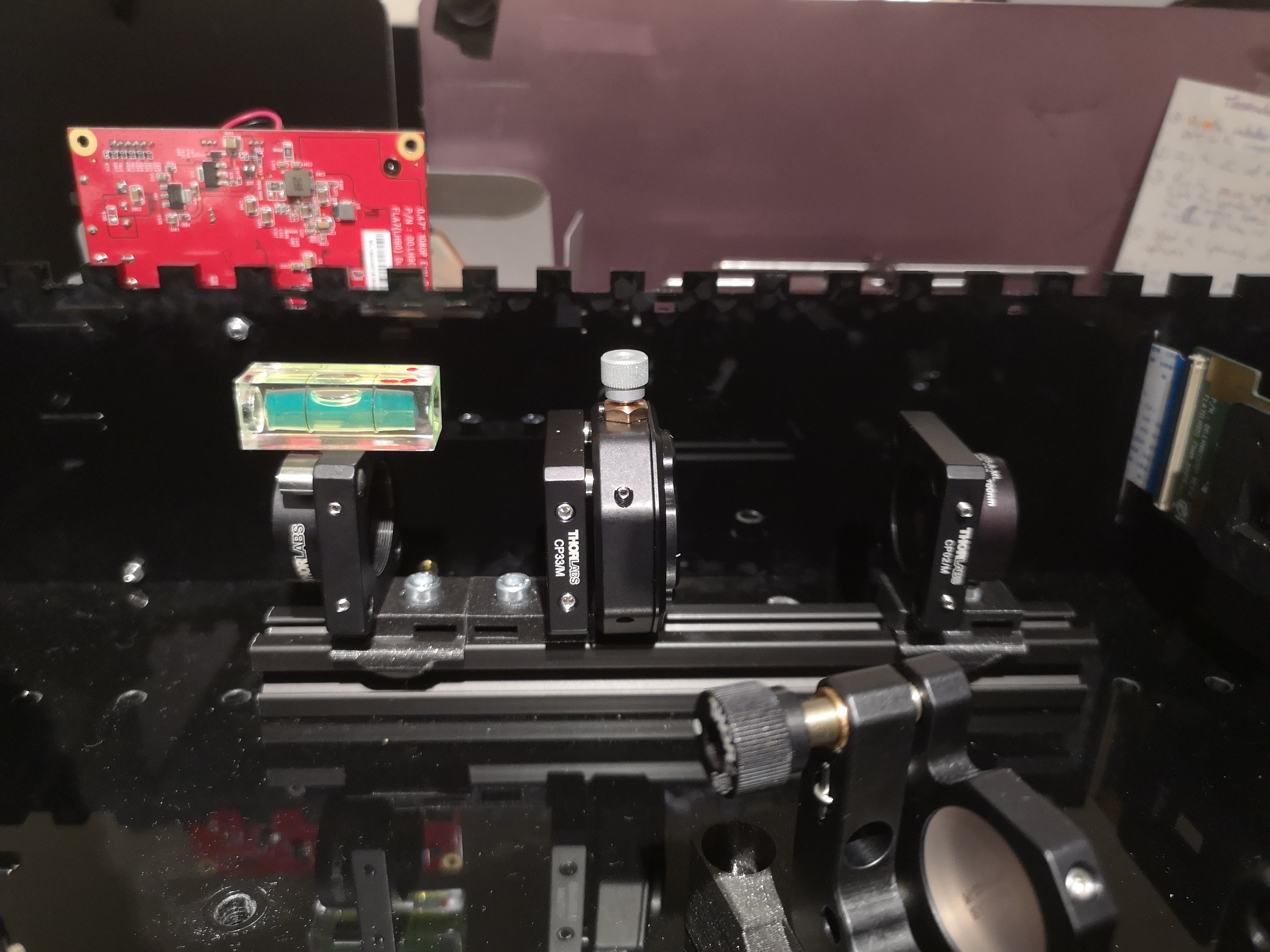
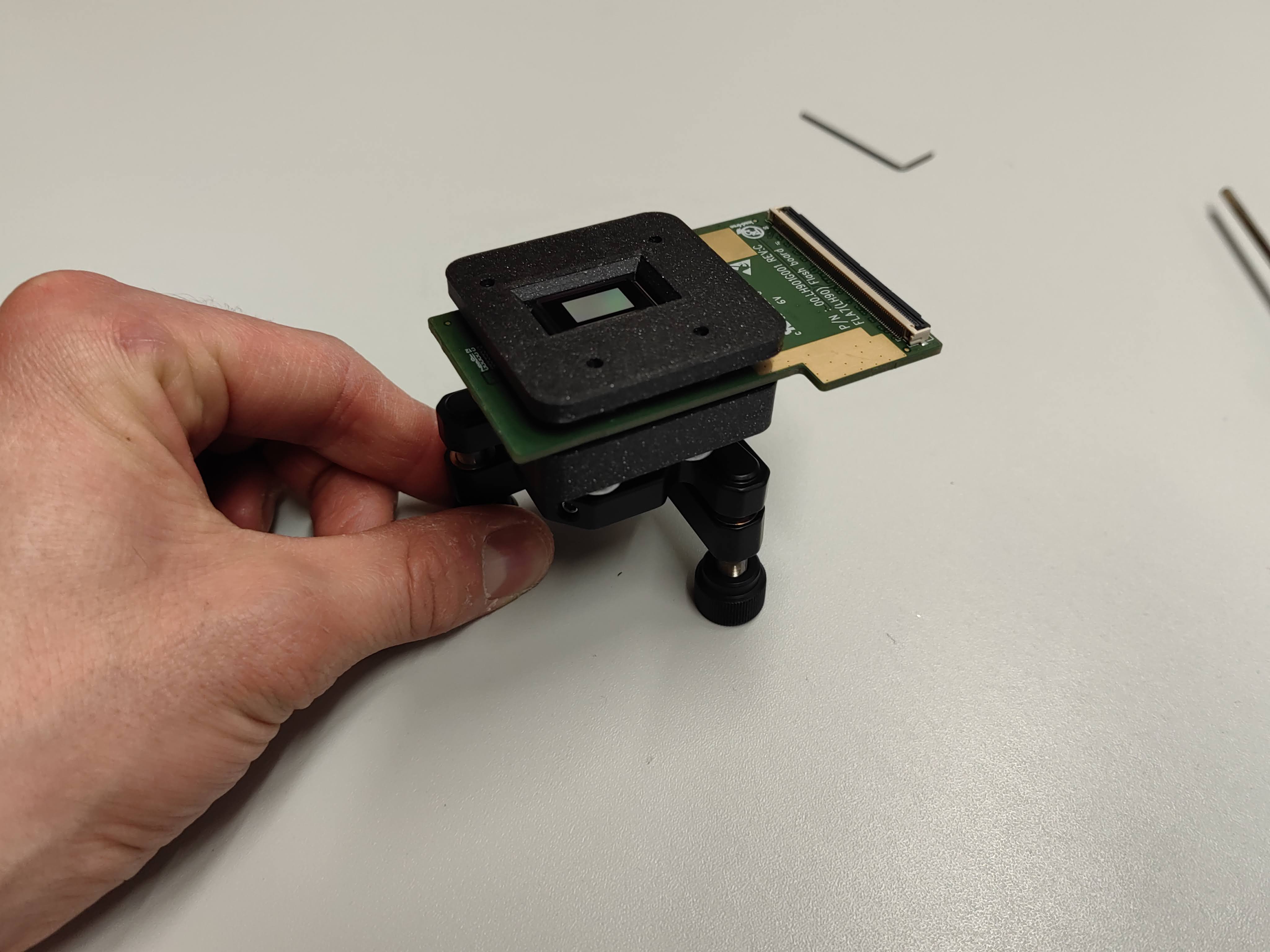
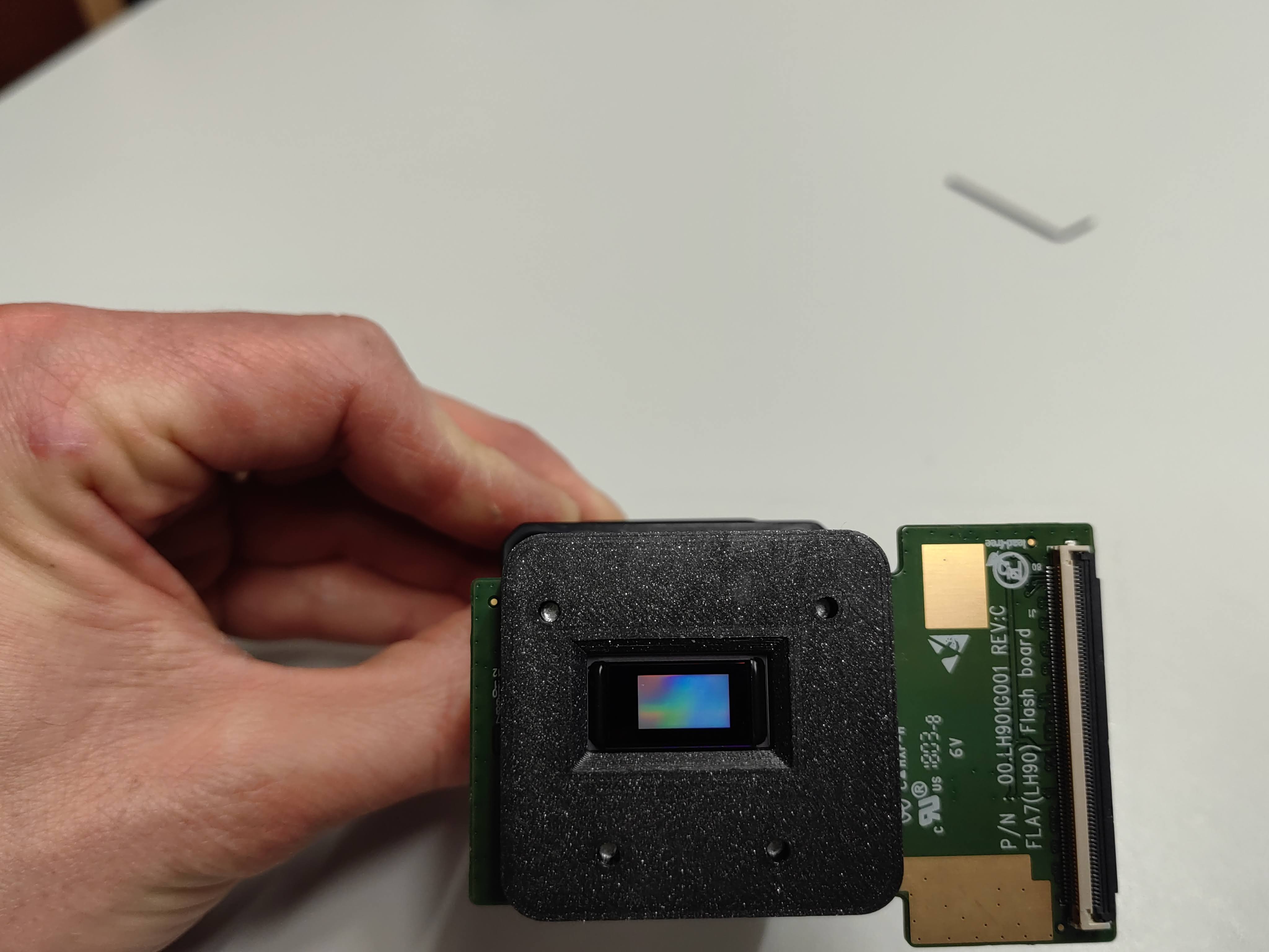
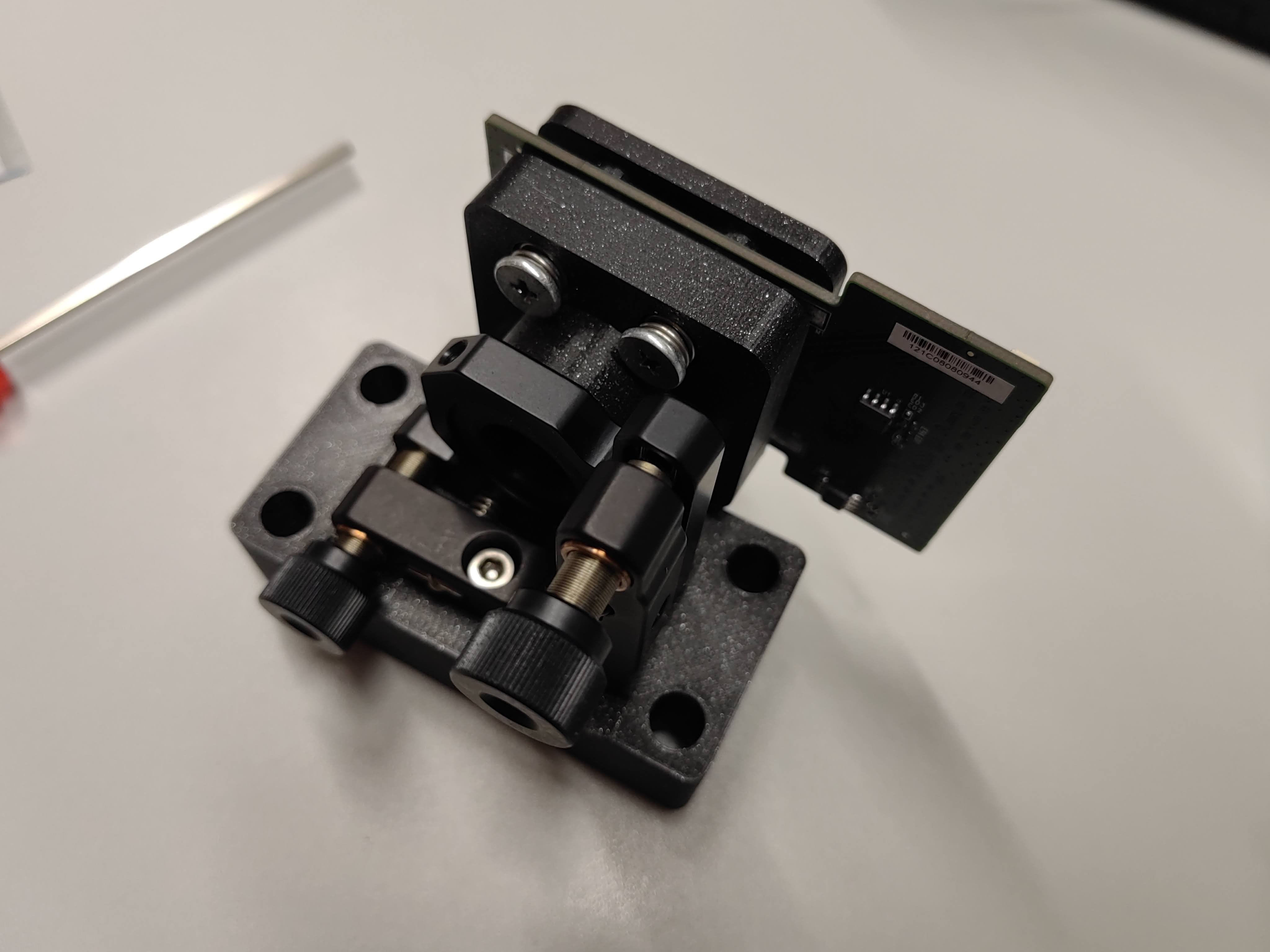
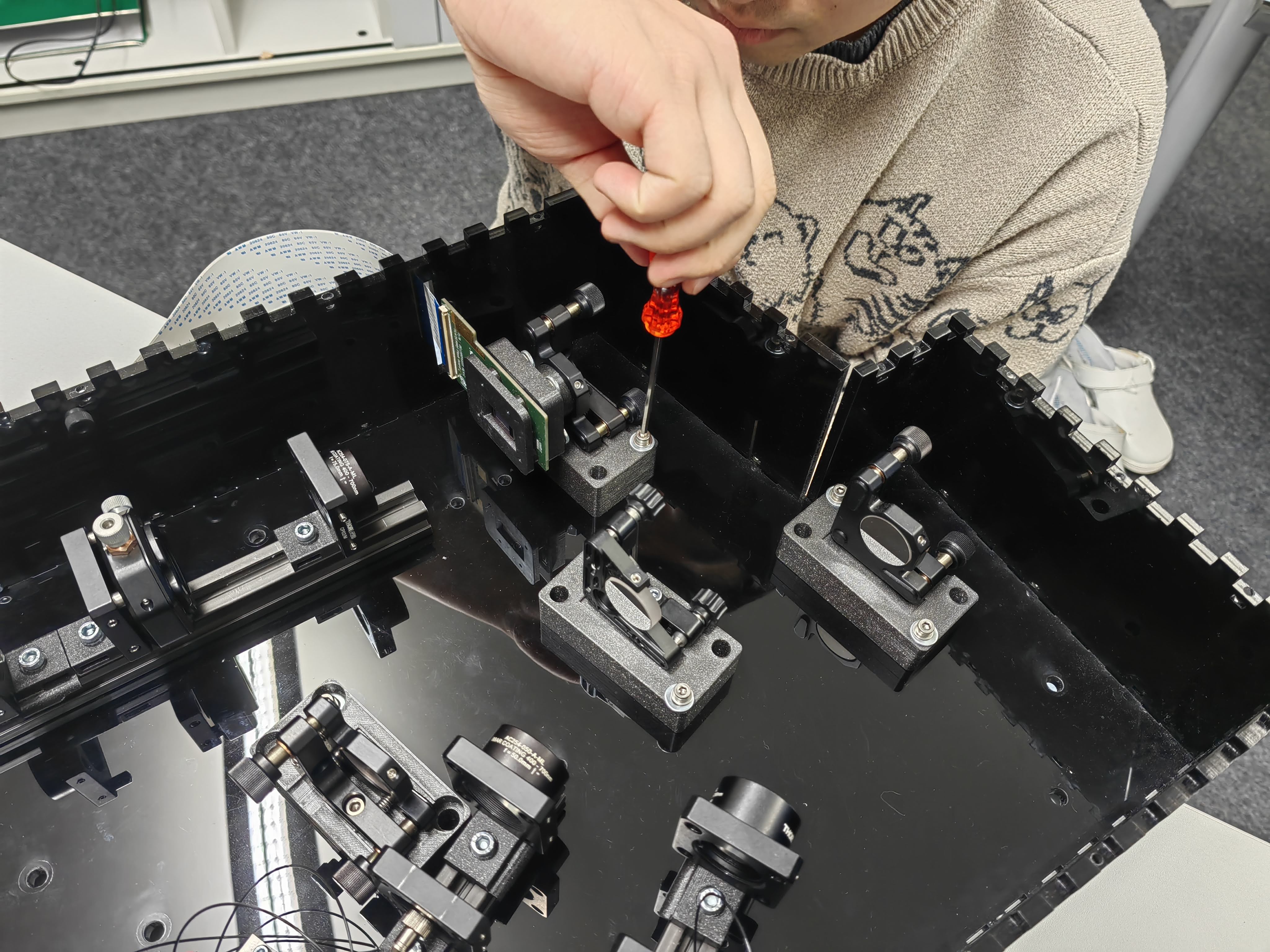
DMD is using similar principle connecting to the mirror mount. Before lock the screw, try to rotate the DMD, make sure the sensor edge remains horizontally.
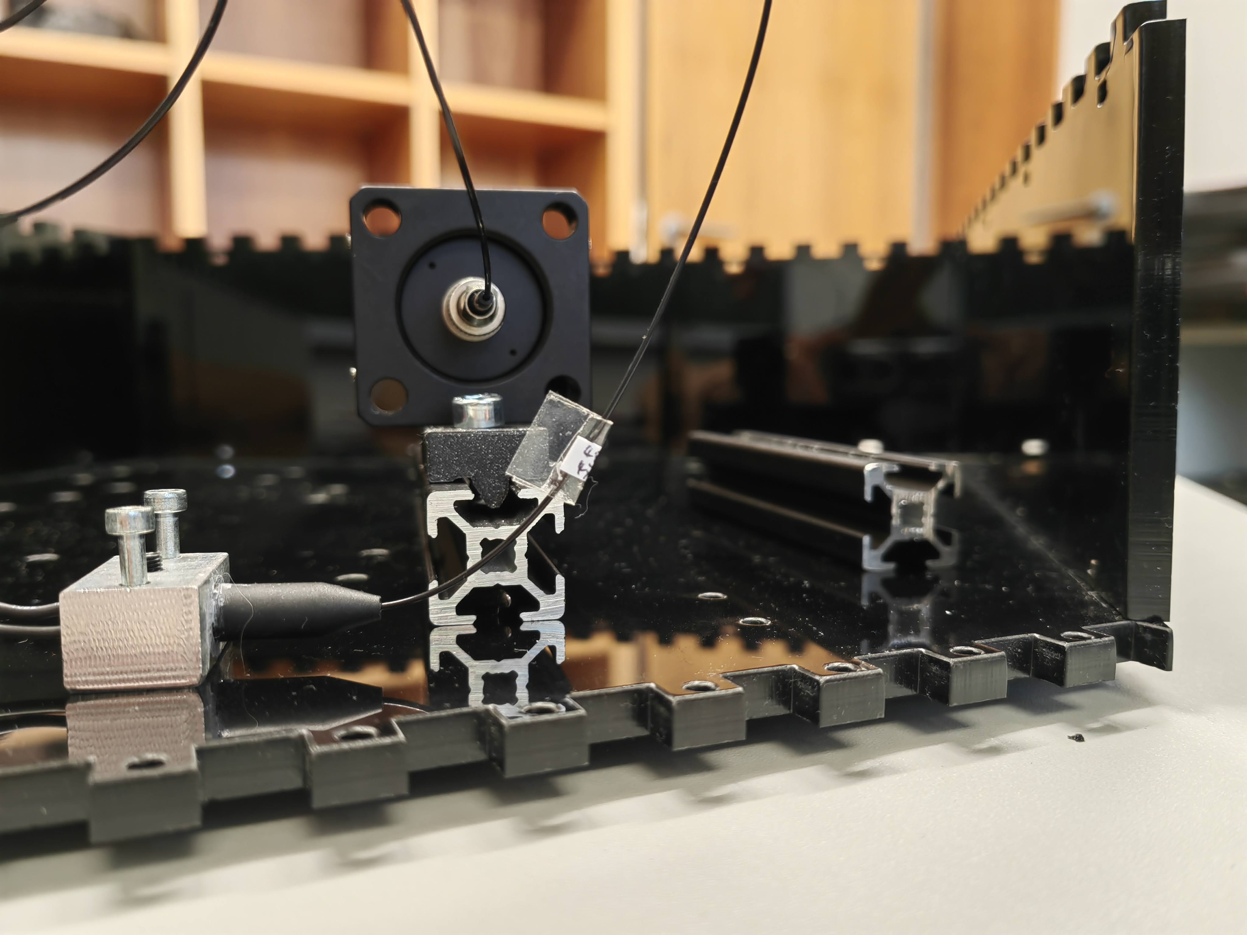
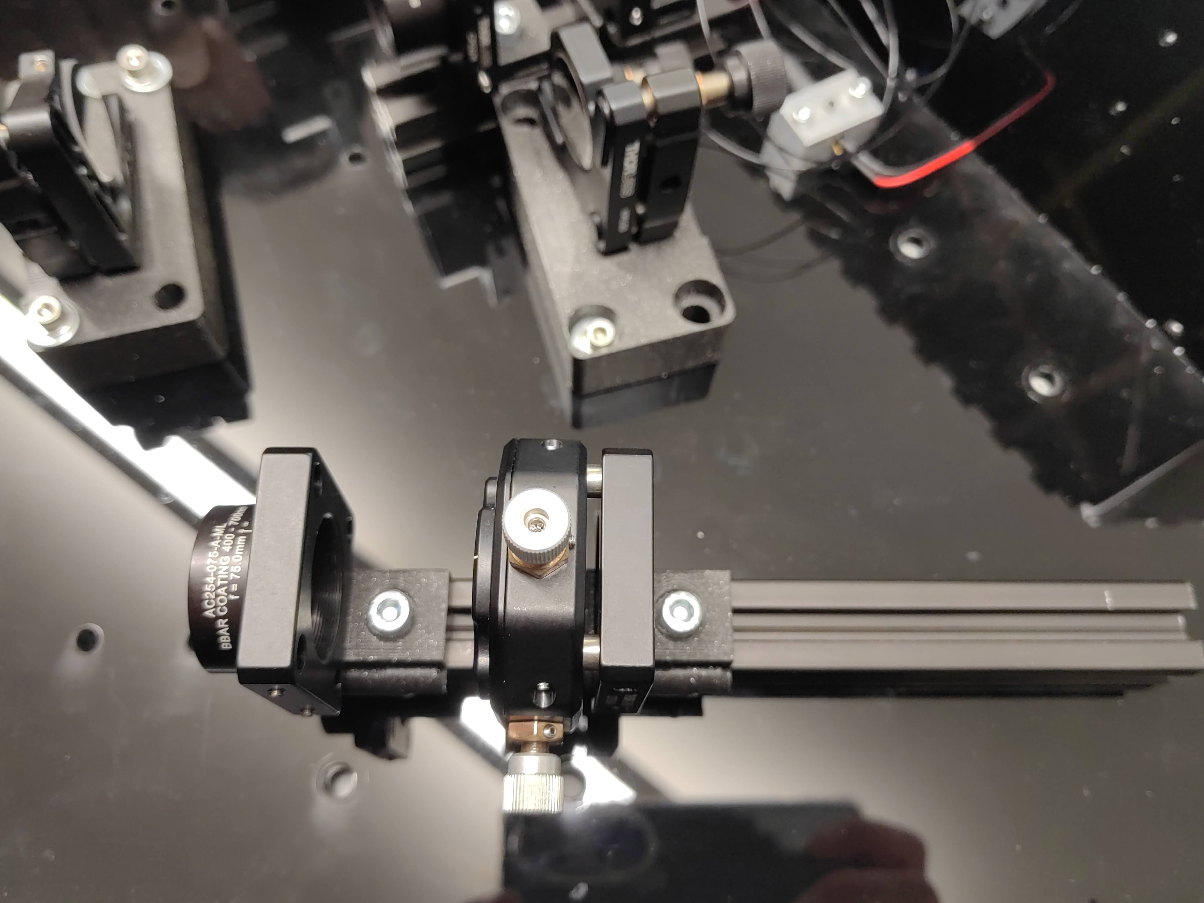
Cage plates are connected to a (how does it called) which can hook onto the aluminium profiles with position adjust possibility.
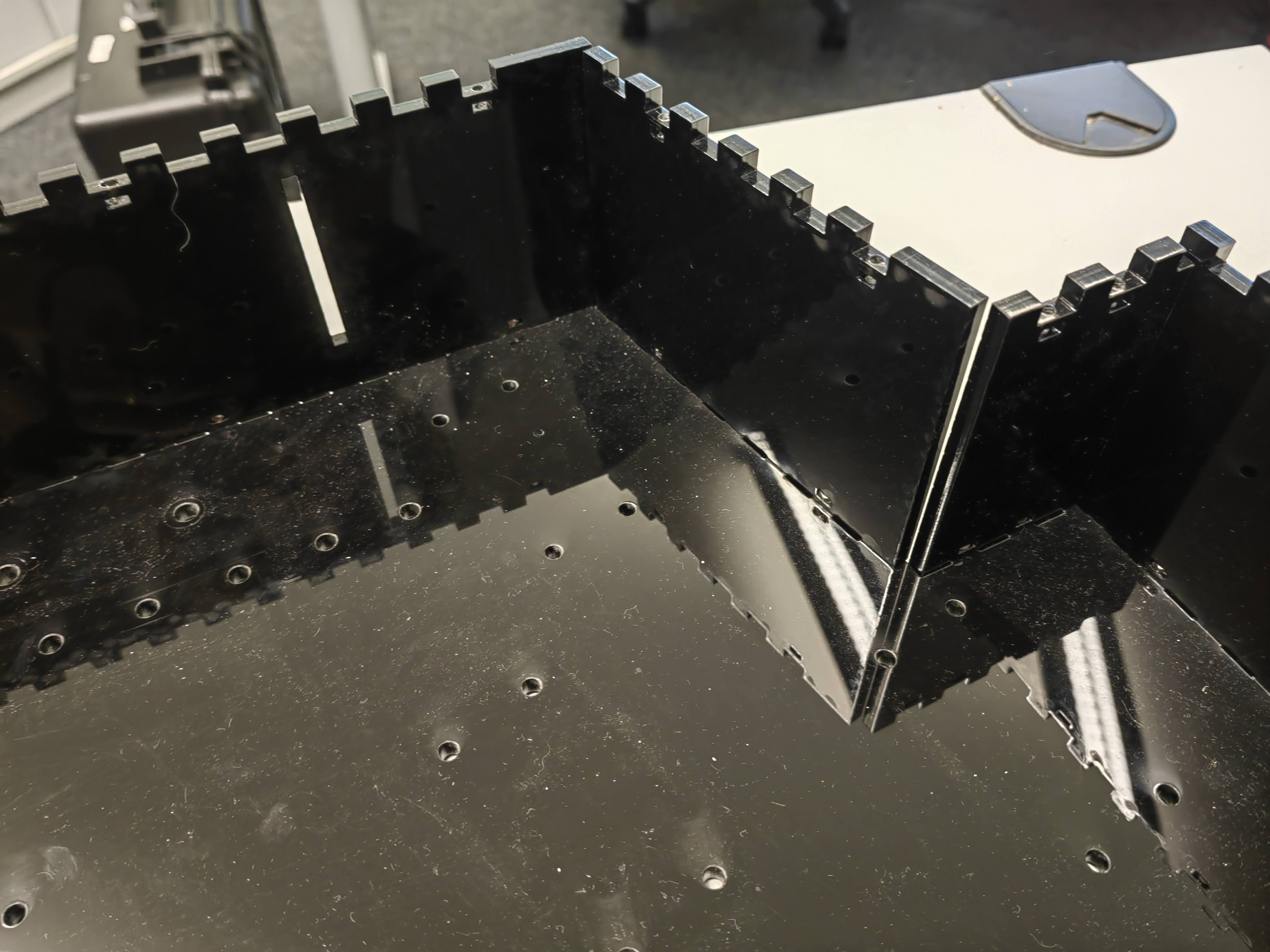
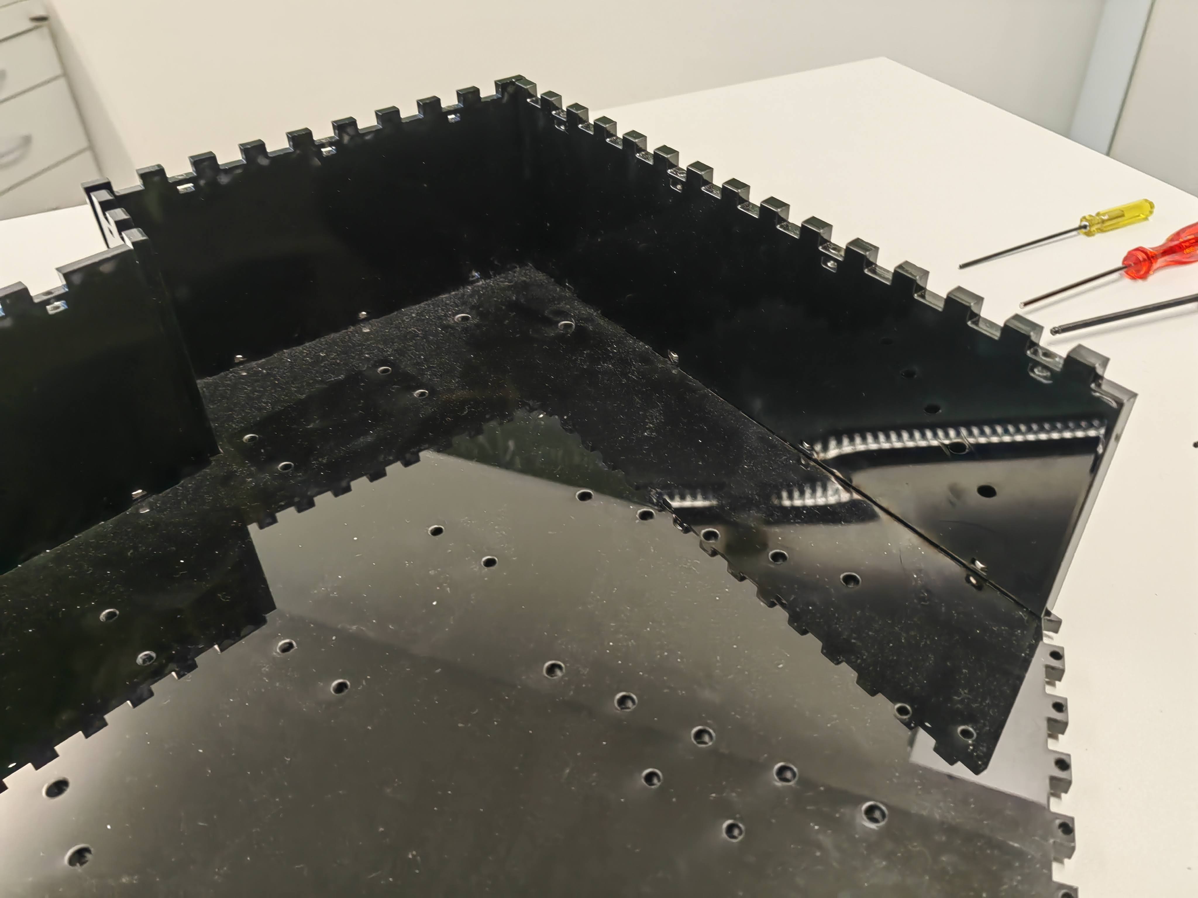
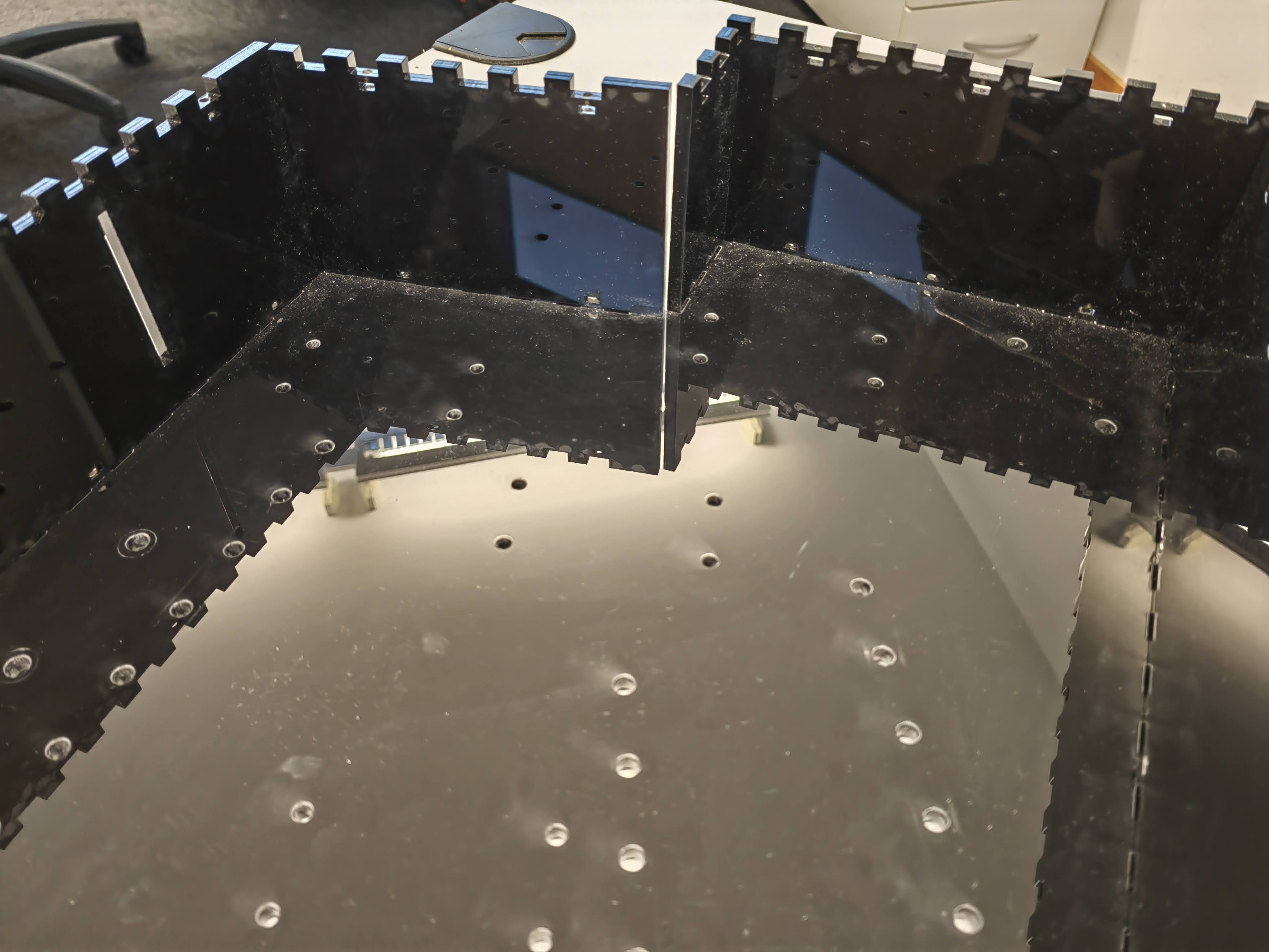
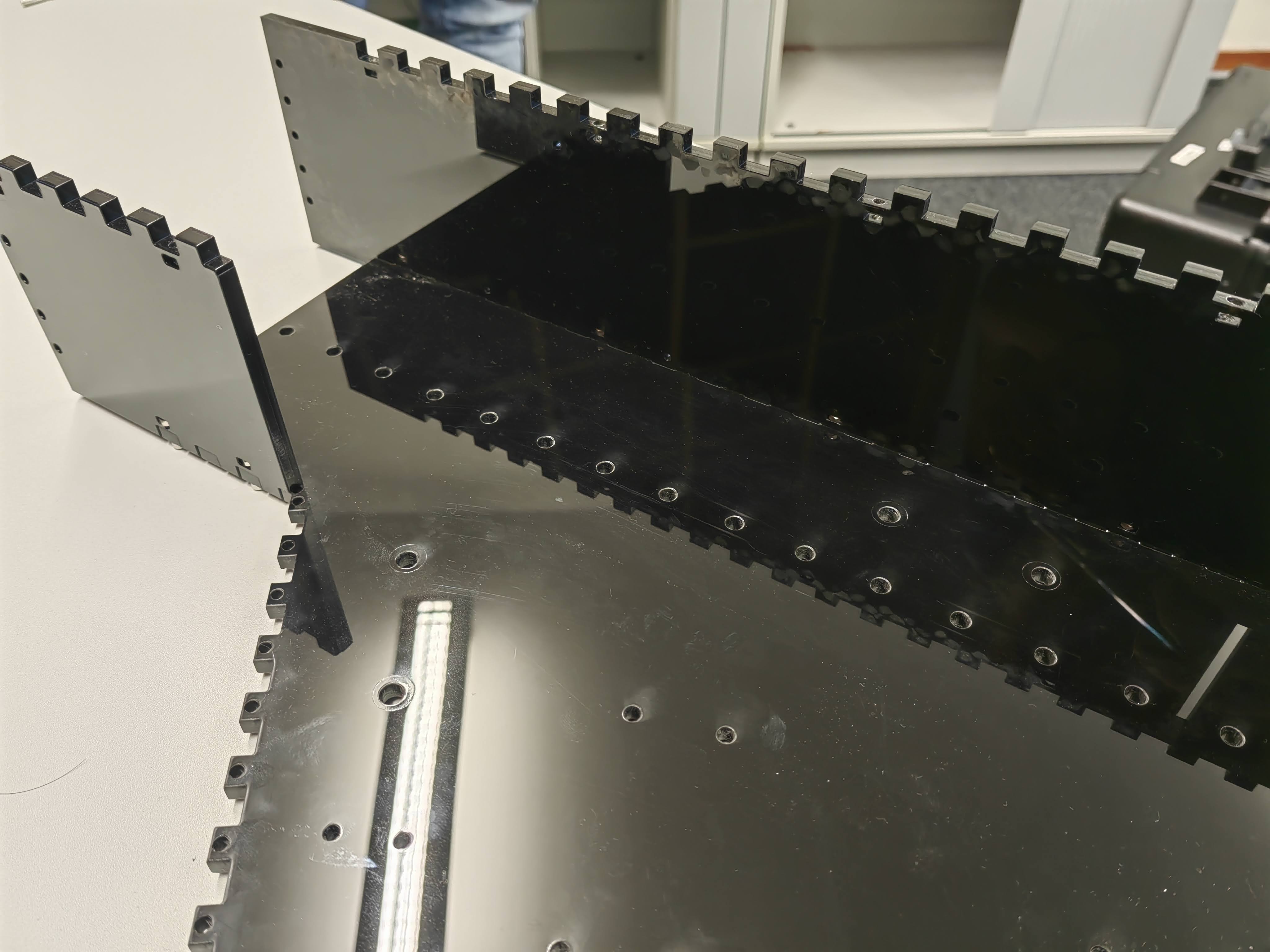
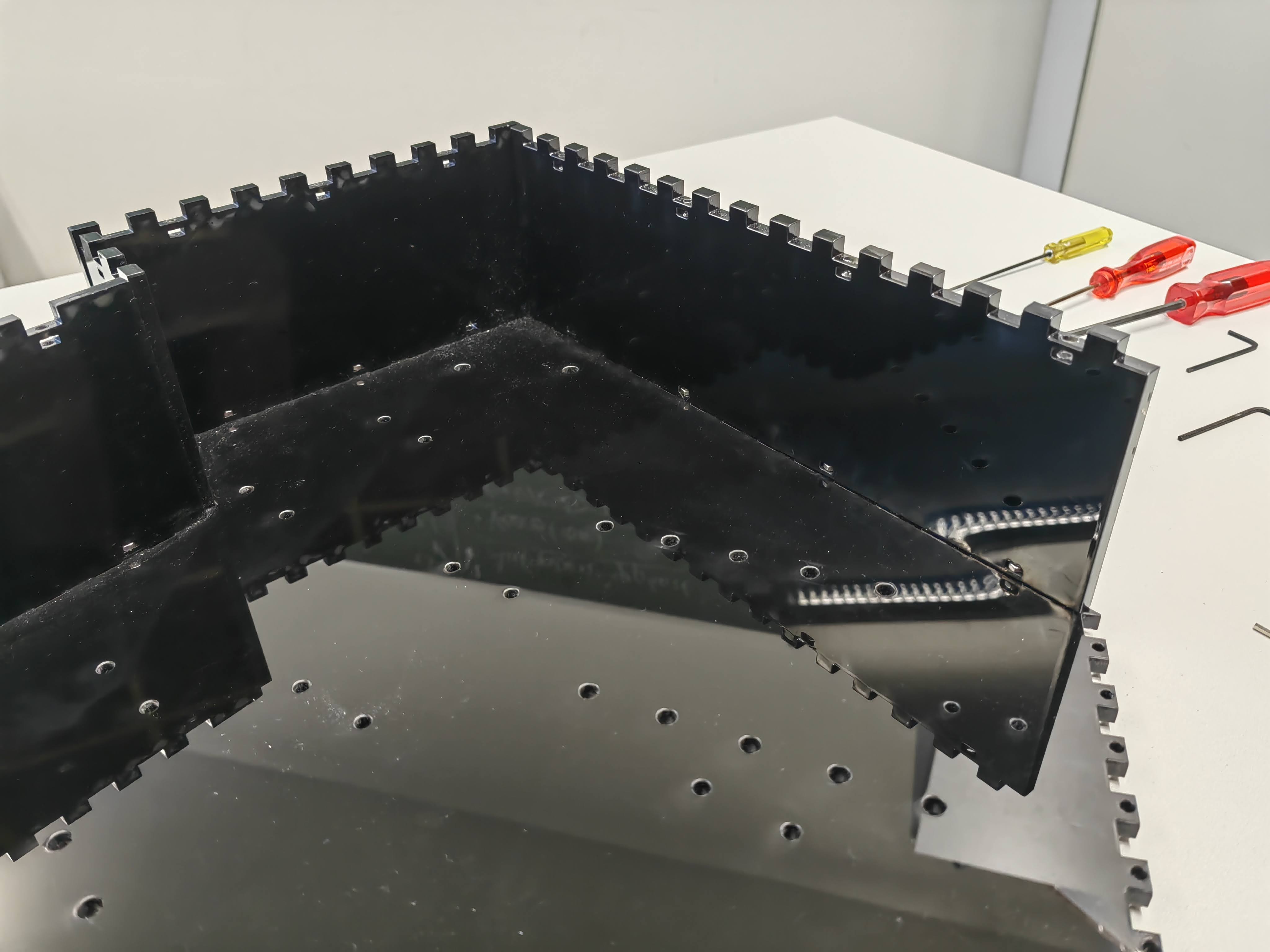
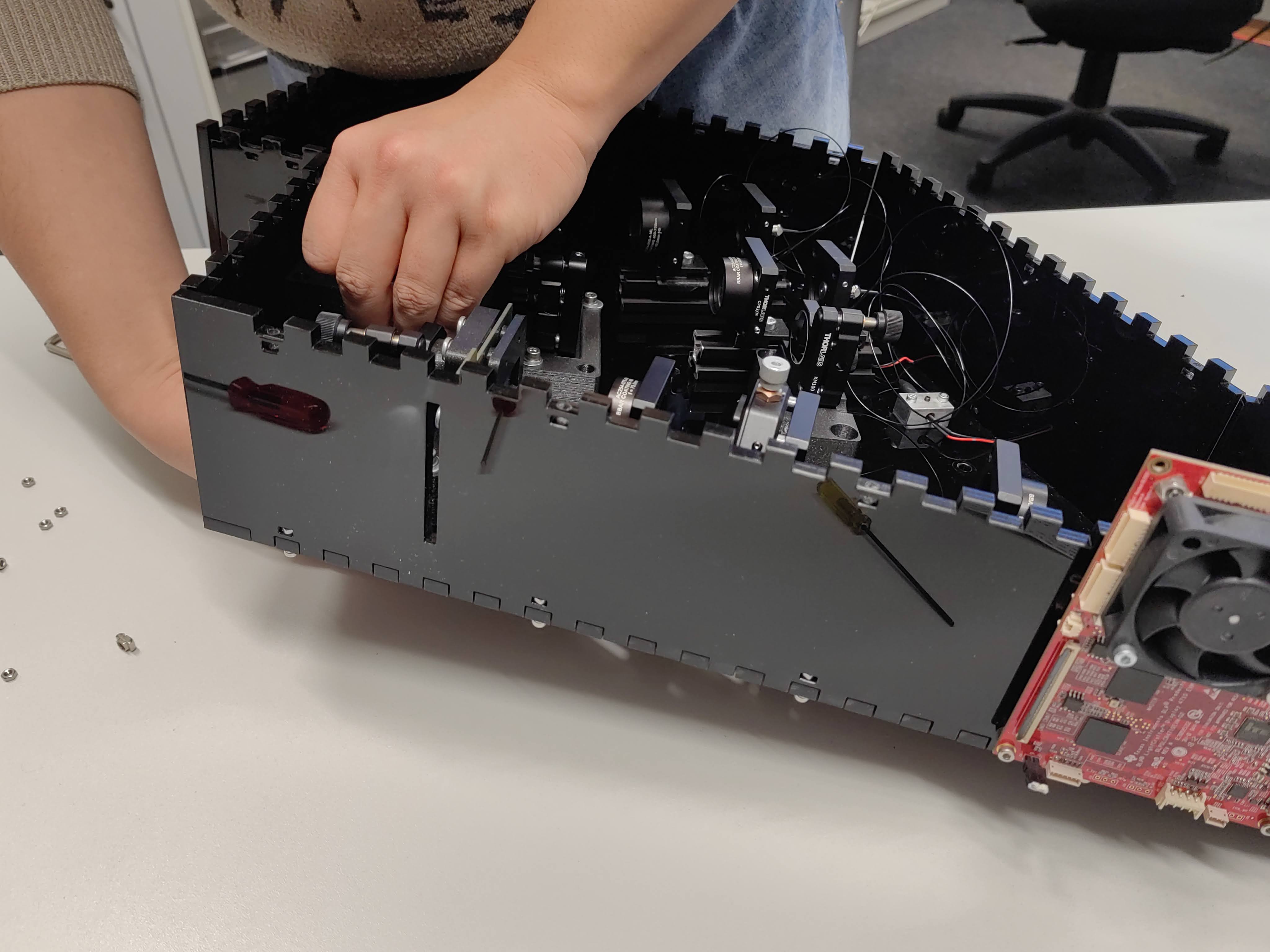
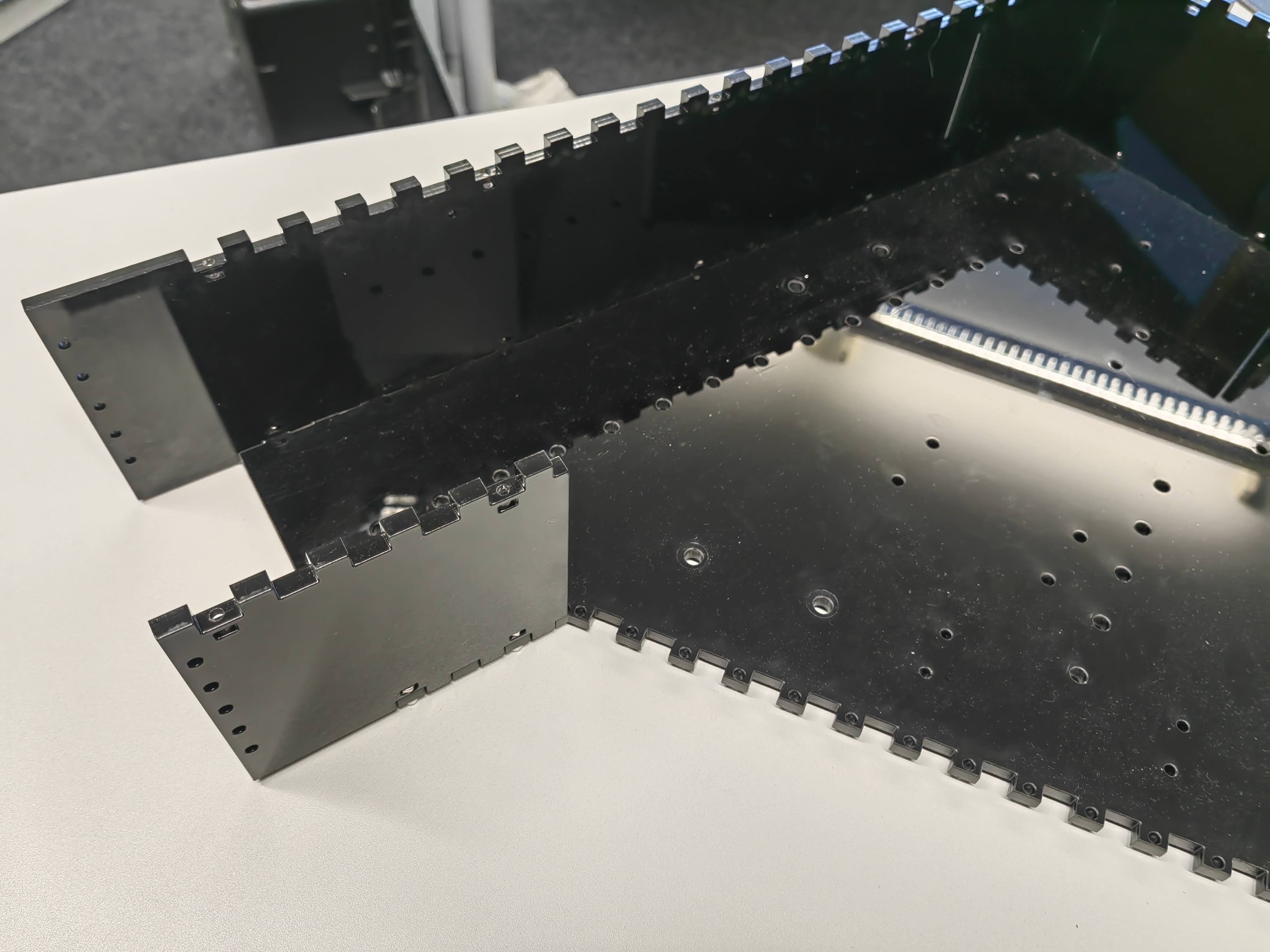
- Mounting the enclosure side wall to the ground plate
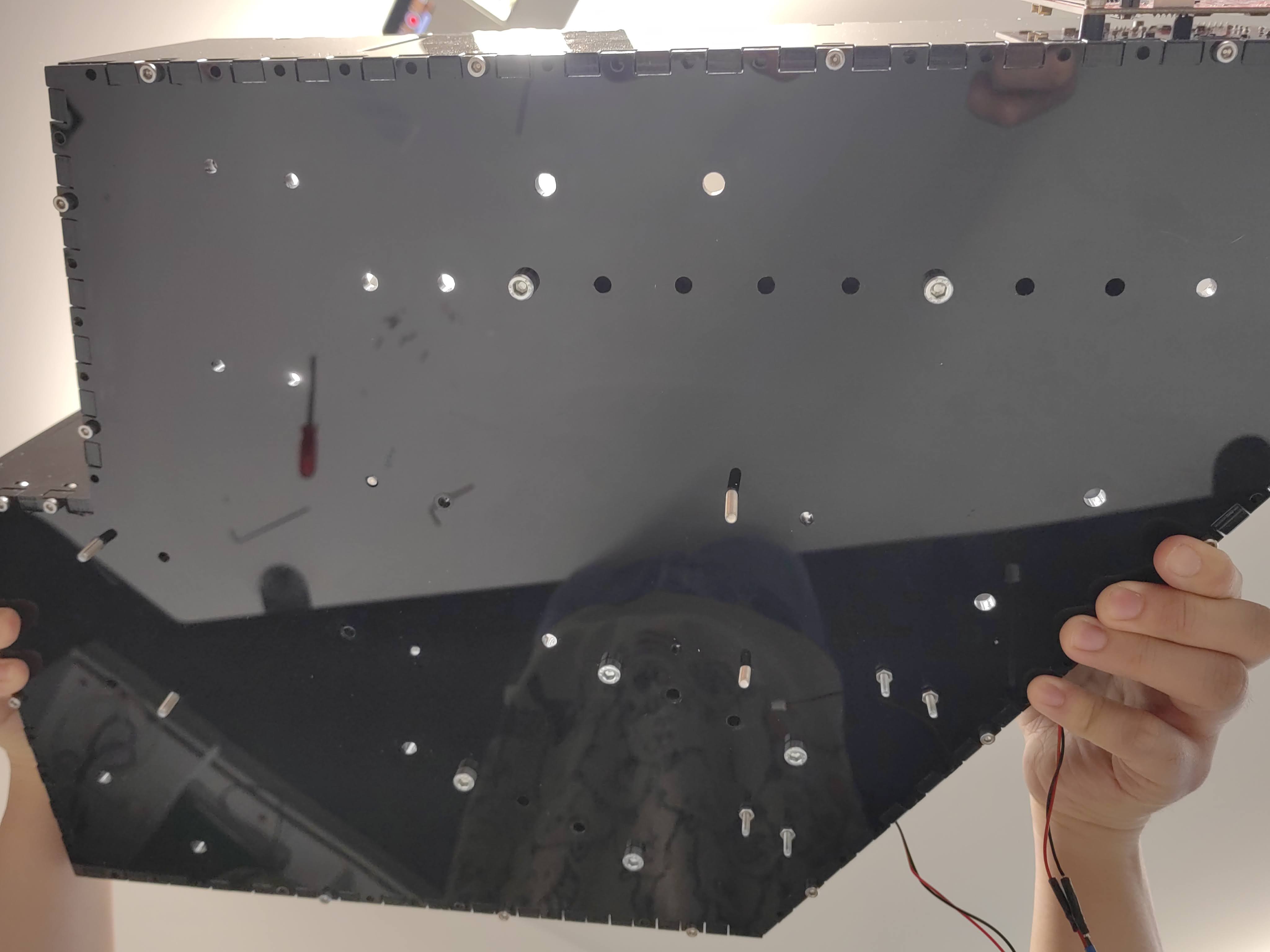
The side walls are connected to the ground board with M3 screws. Screw nuts are placed inside the wall and bonded with the screw. In the side walls, there is one piece slightly different then others, with 2 holes near the zig-zag edge. It is done in purpose, in order to let the laser power cable go through the enclosure. Keep this wall first free until the laser is mounted to the ground board.
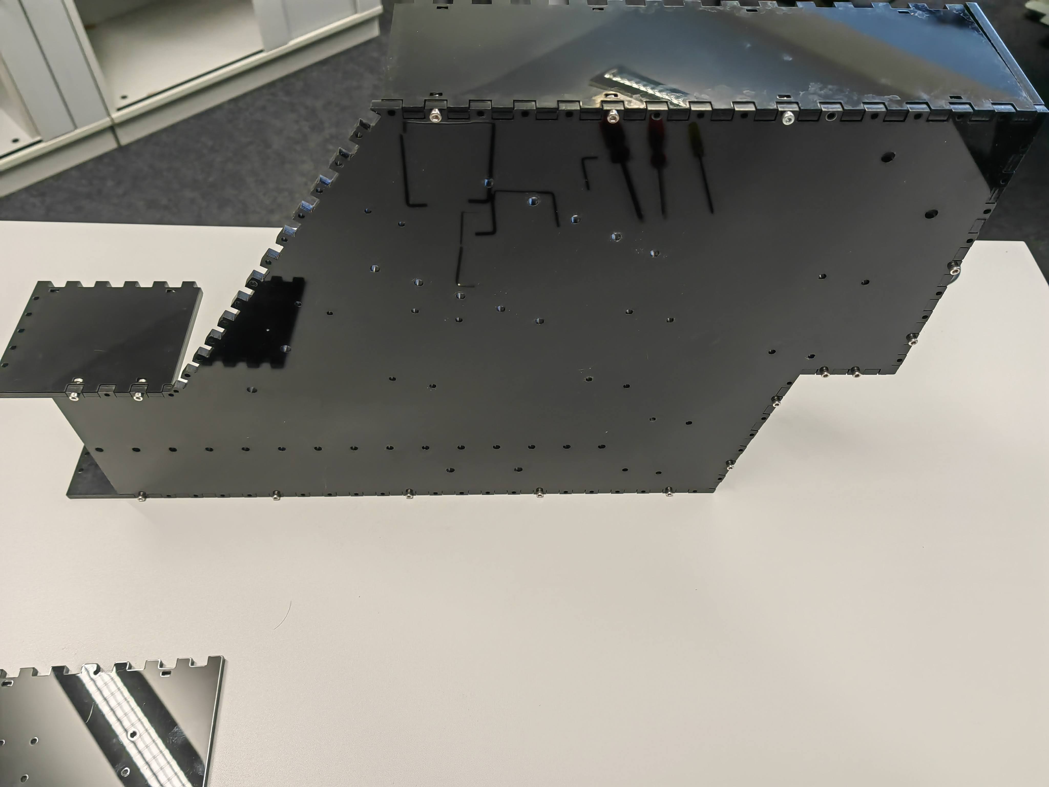
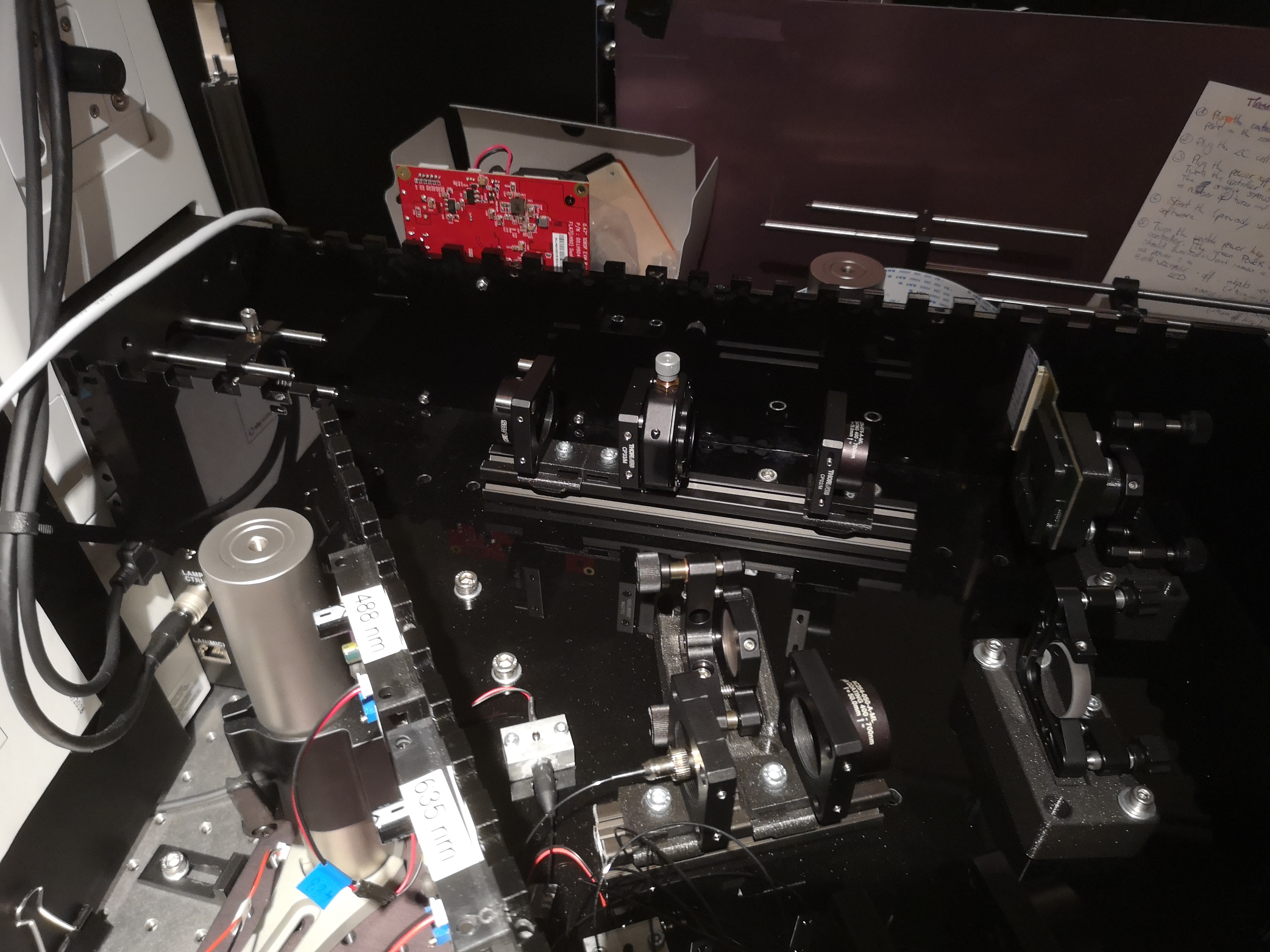
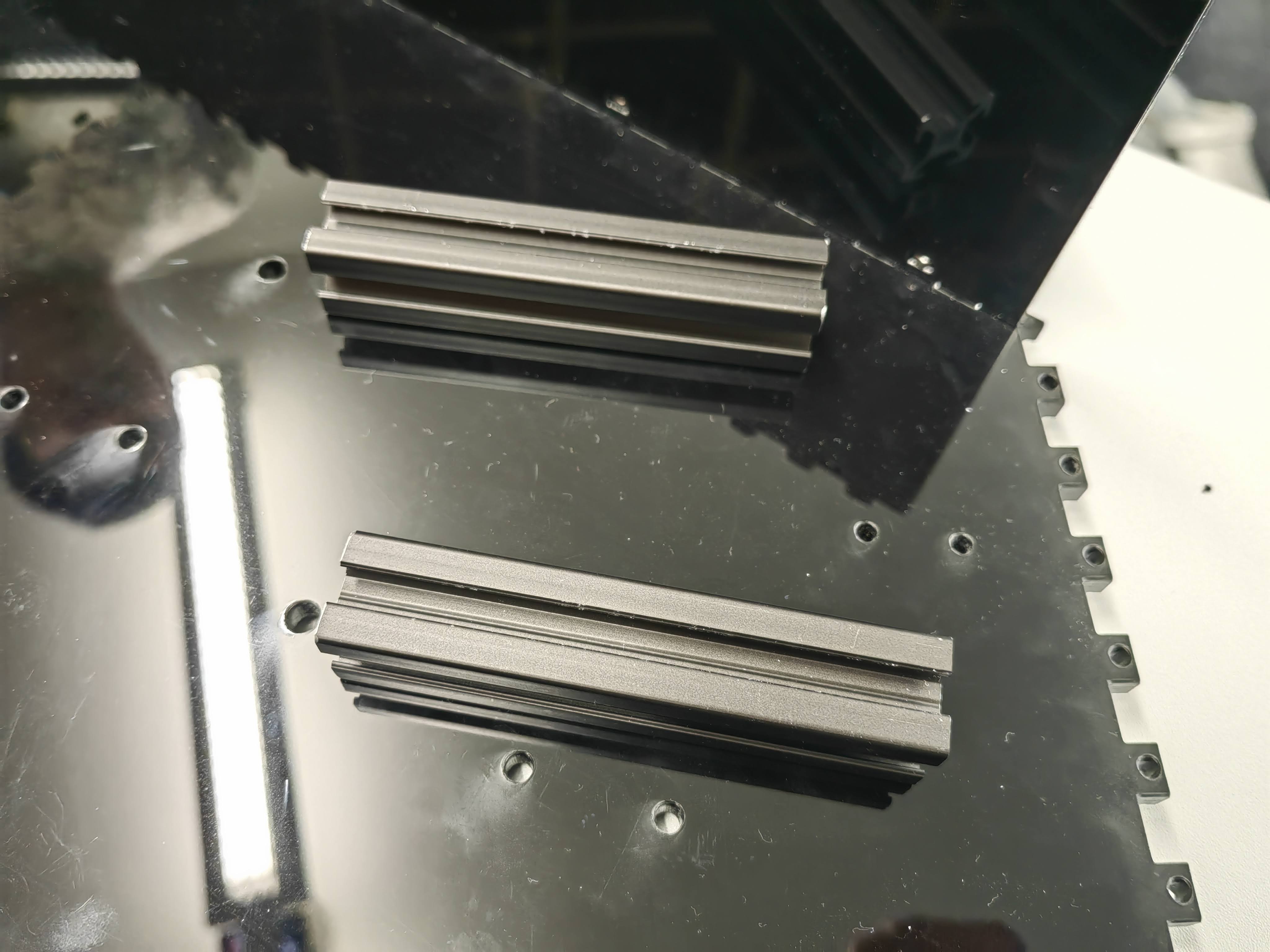
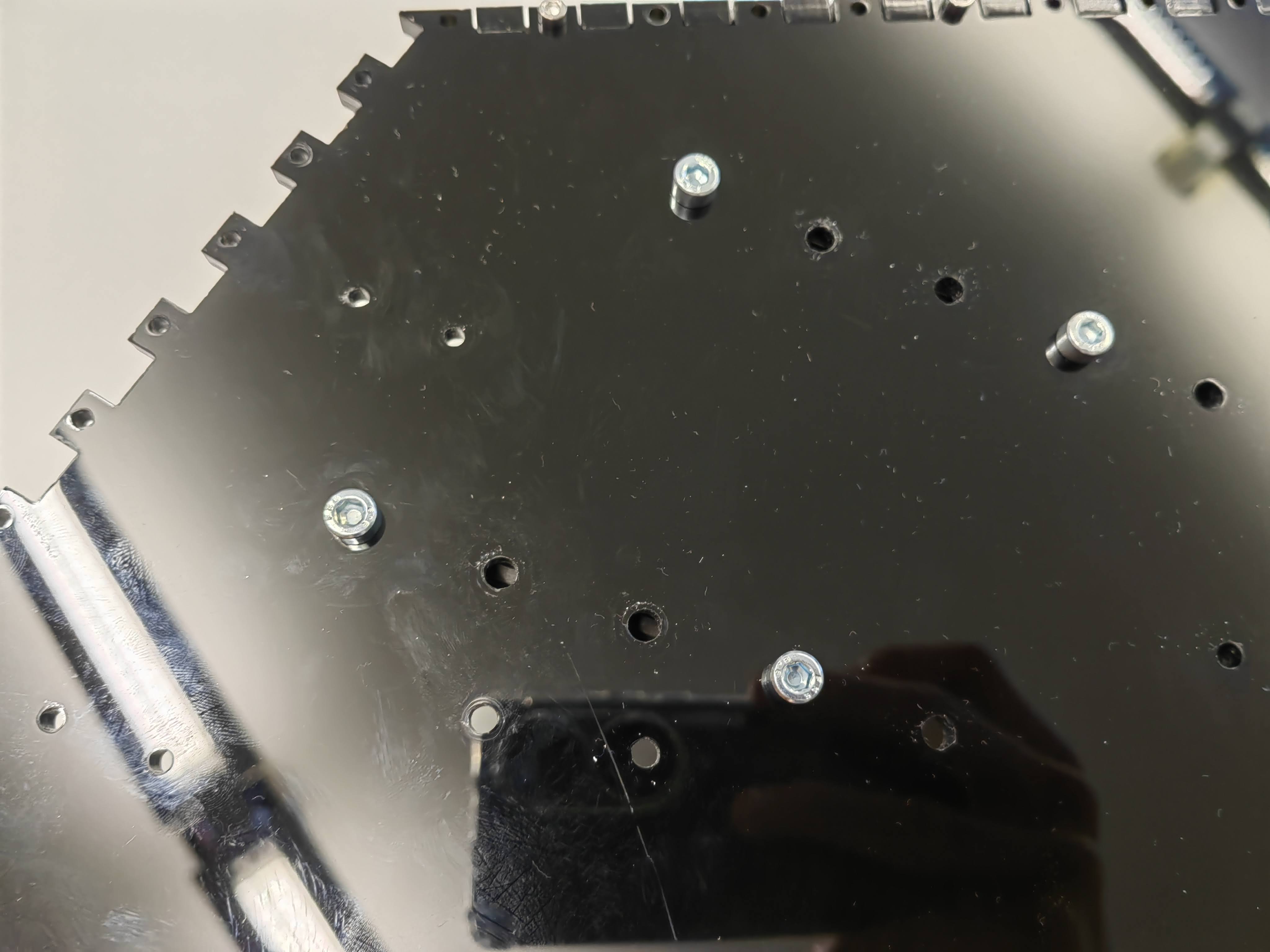
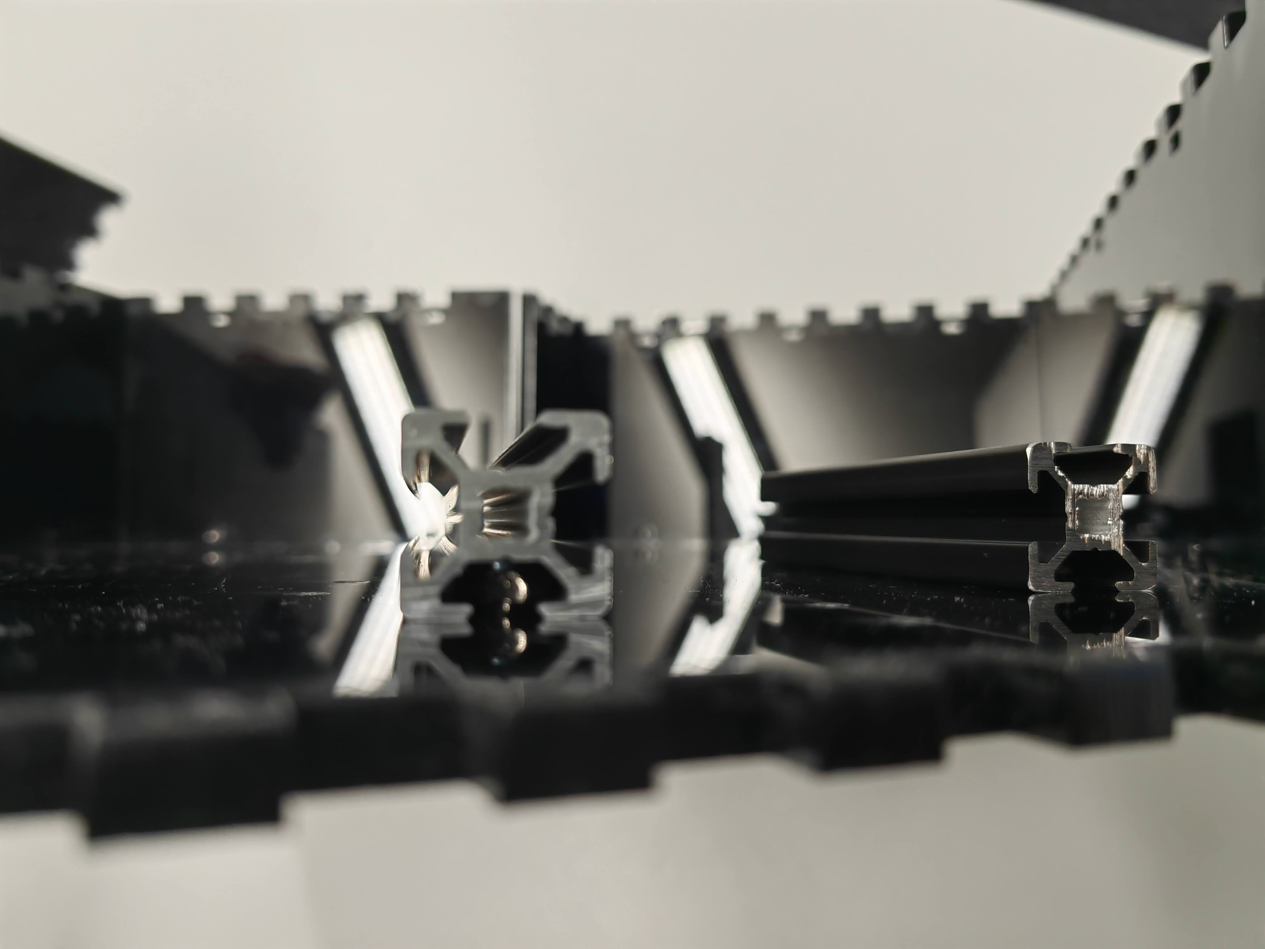
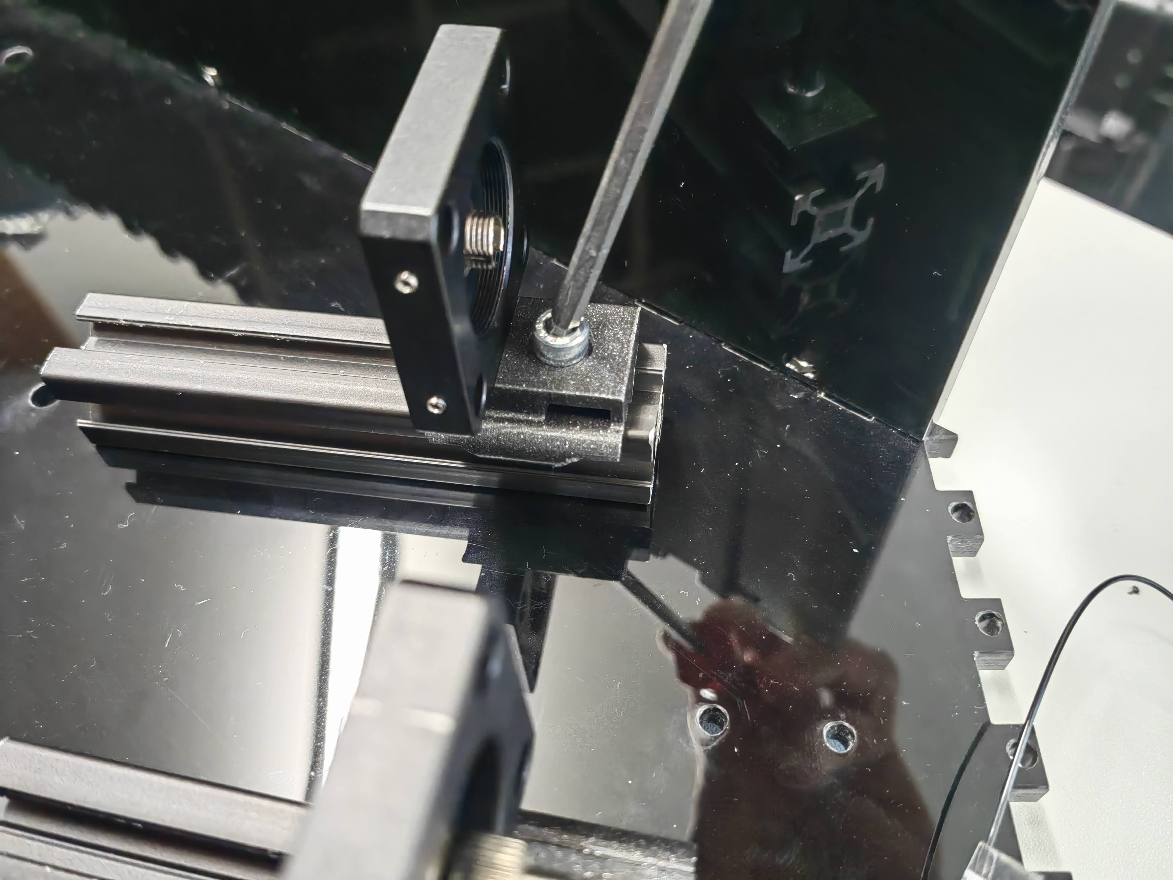
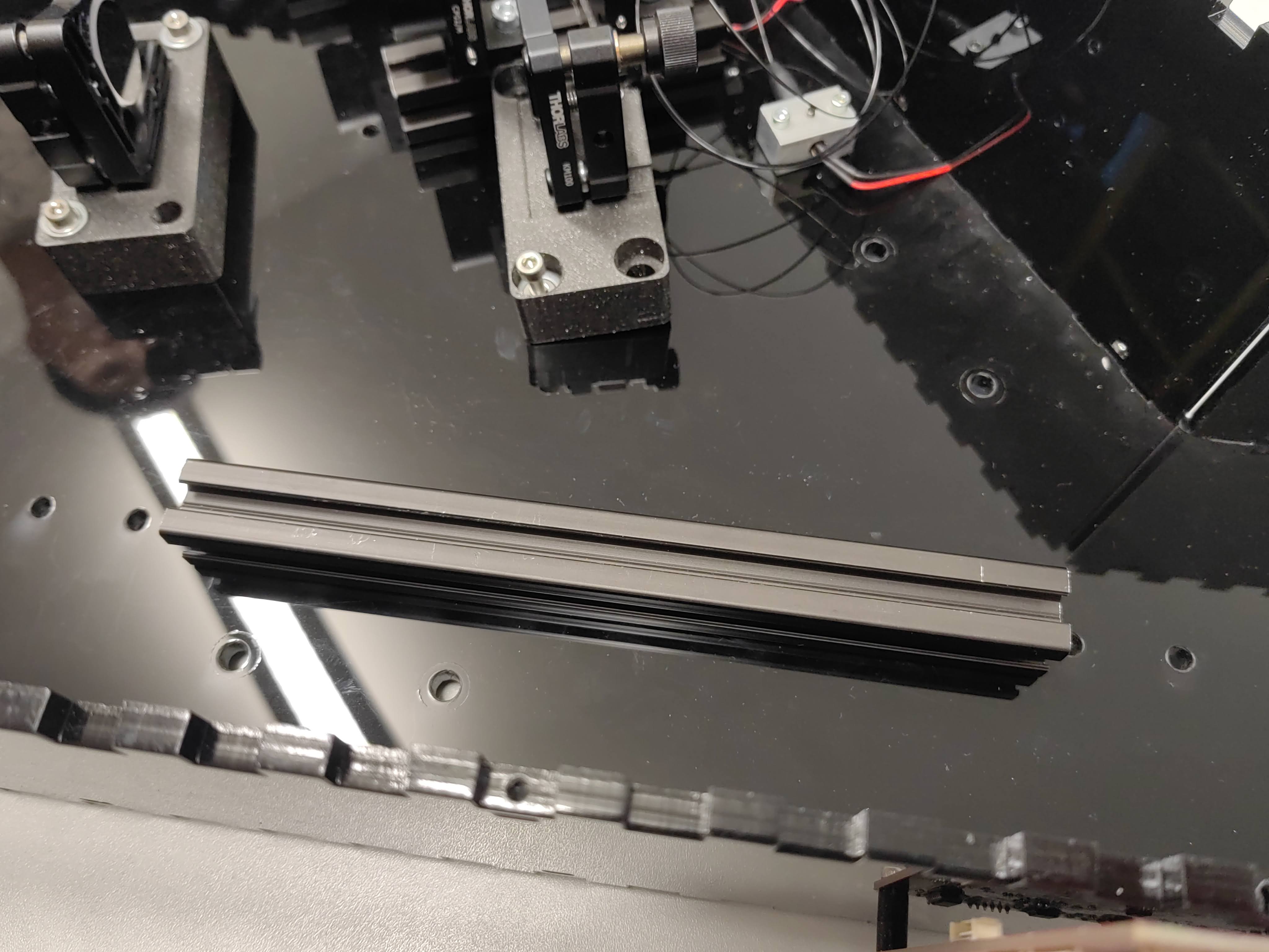
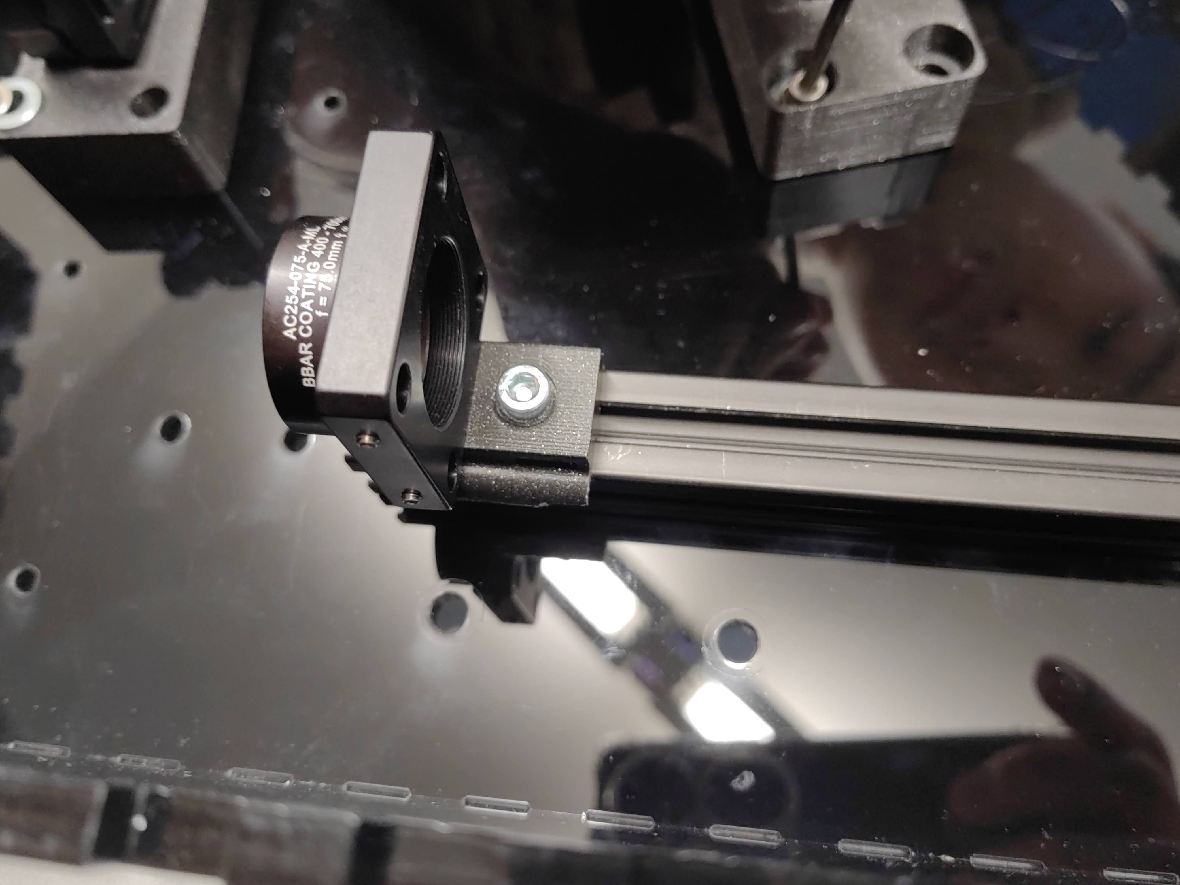
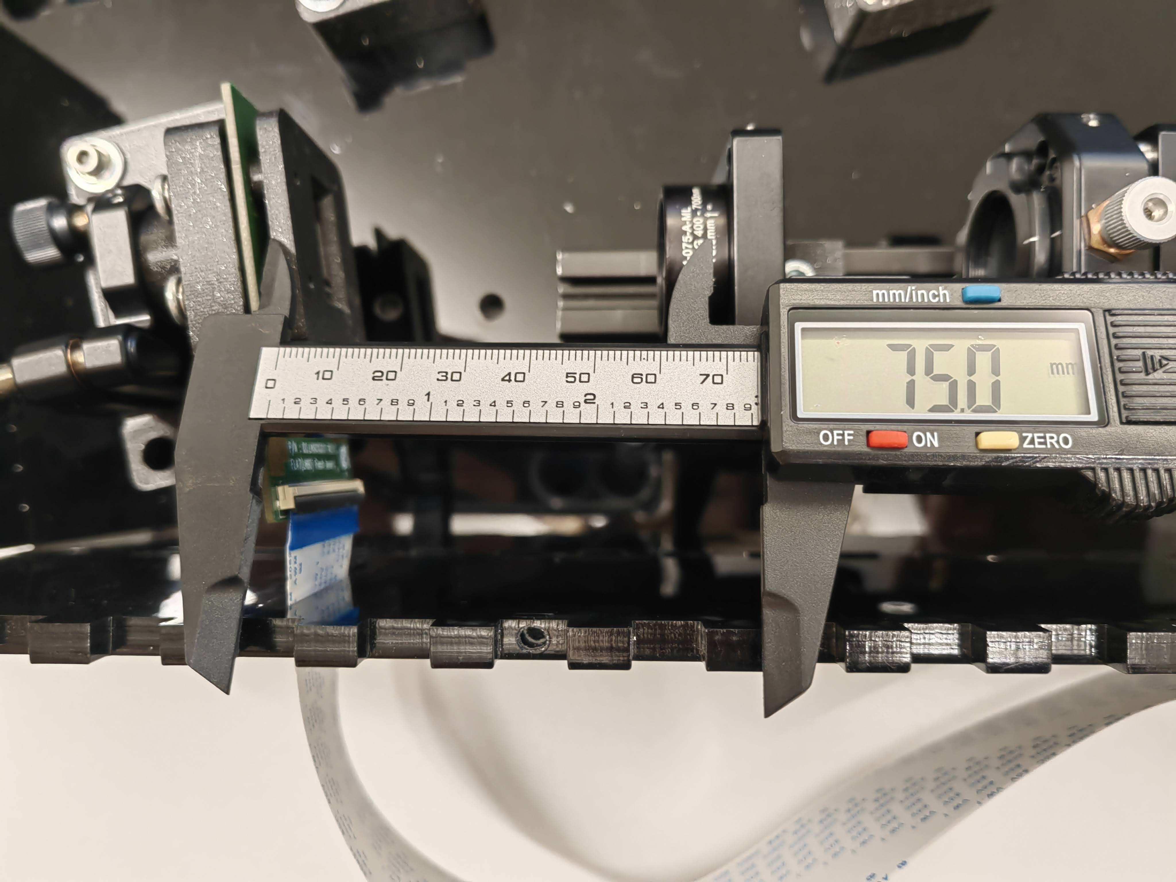
- Fixing the aluminium profile onto the ground plate
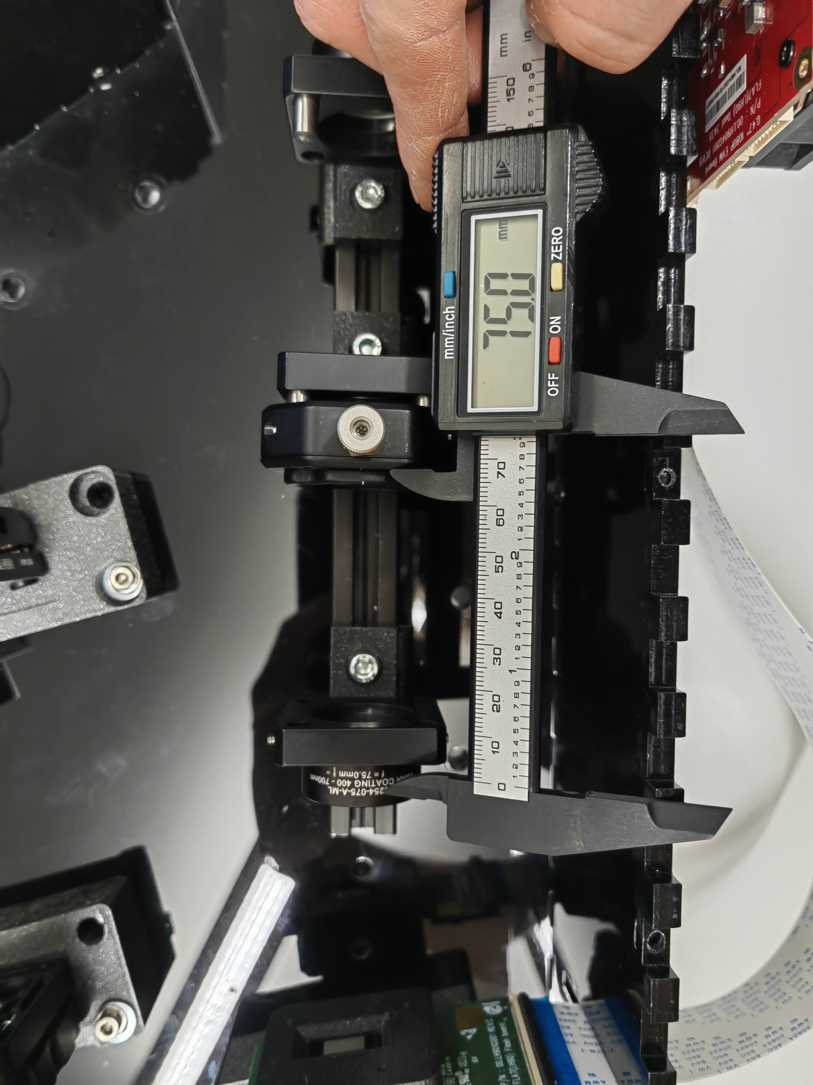
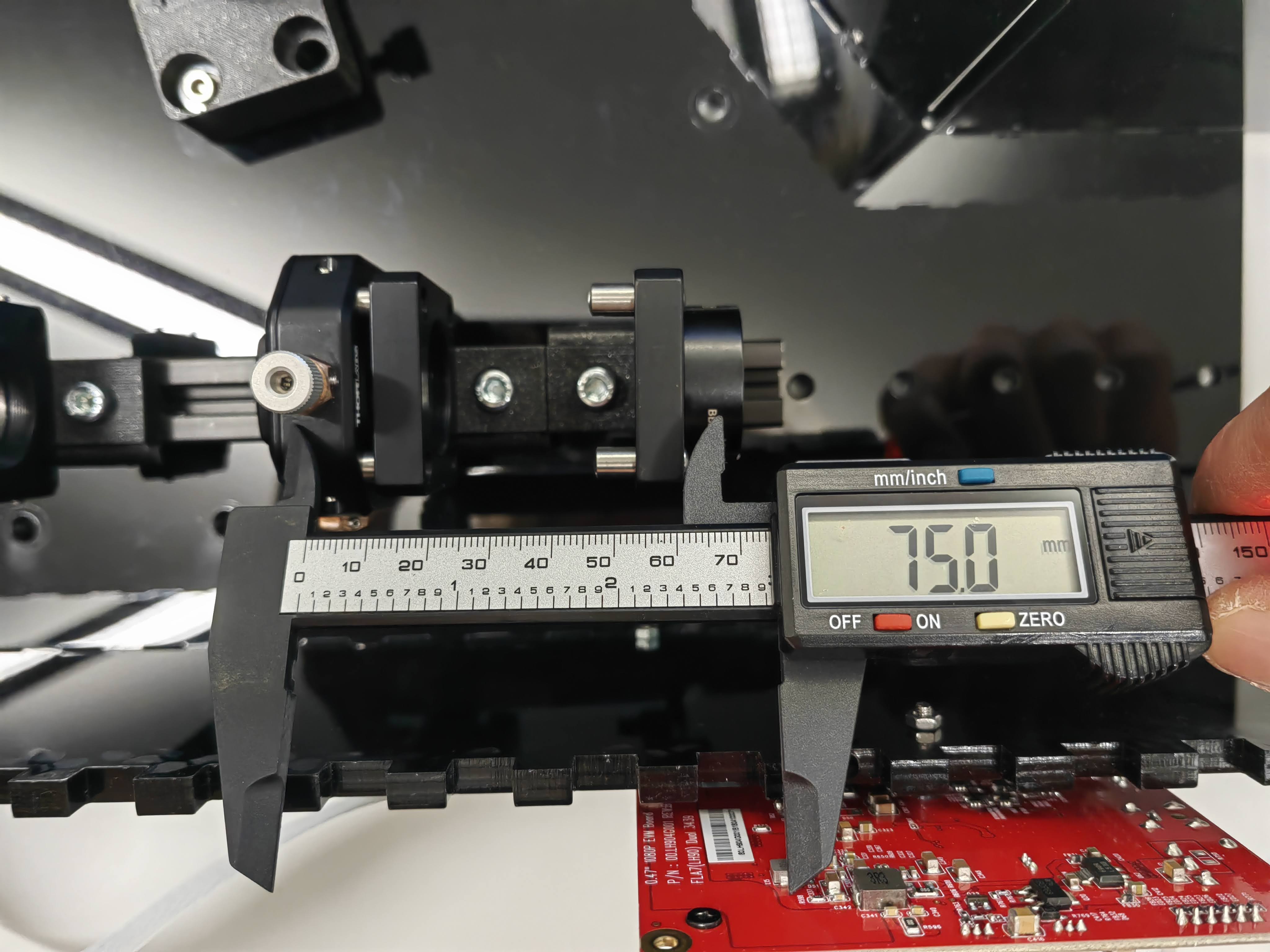
Aluminium profiles are used for laser collimation and conjugated fourier plane. Using hammer nuts and M5 screw to fix profiles on the ground plate. 100mm profiles are used for laser collimation.
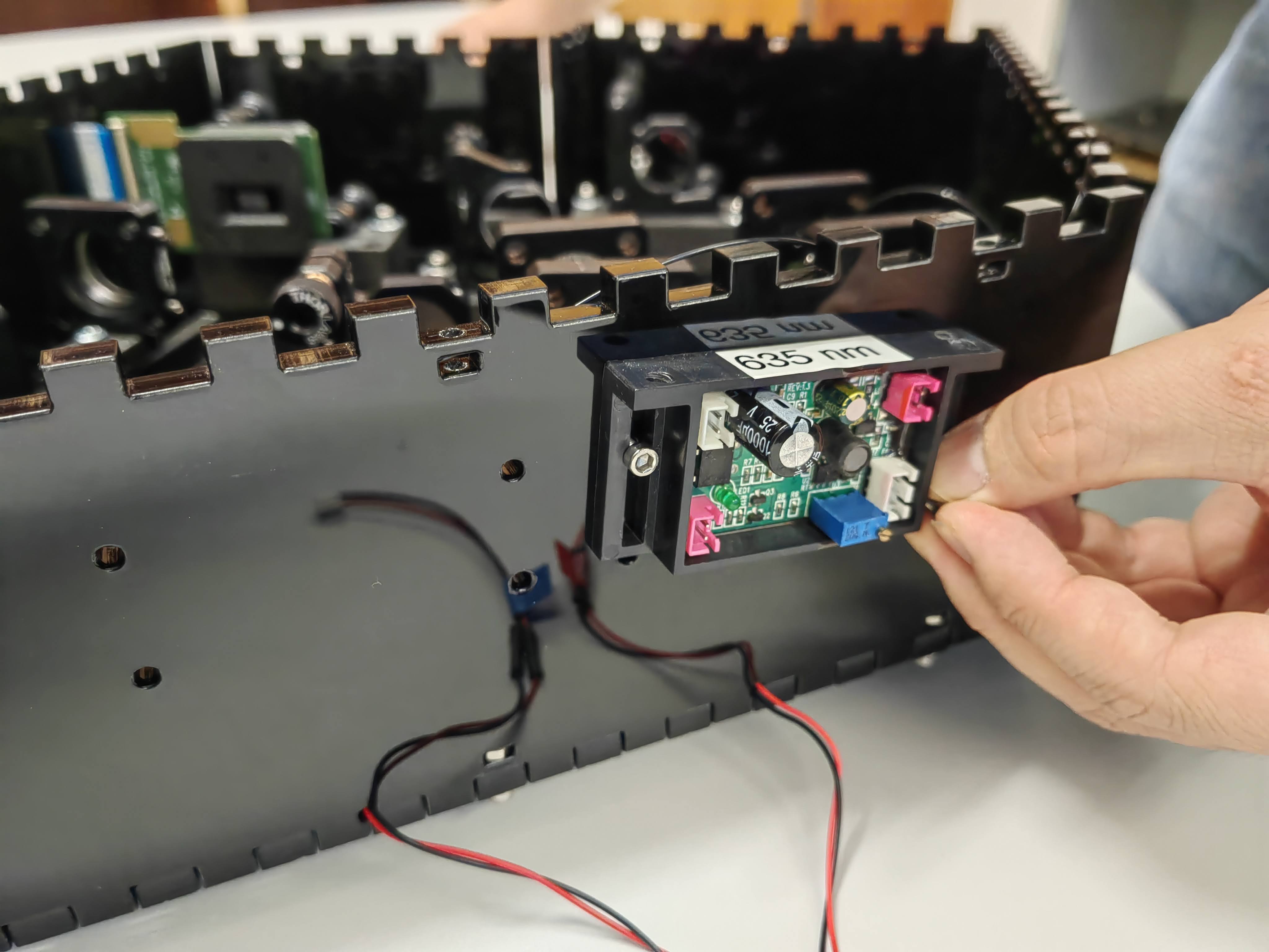
- Mounting the laser
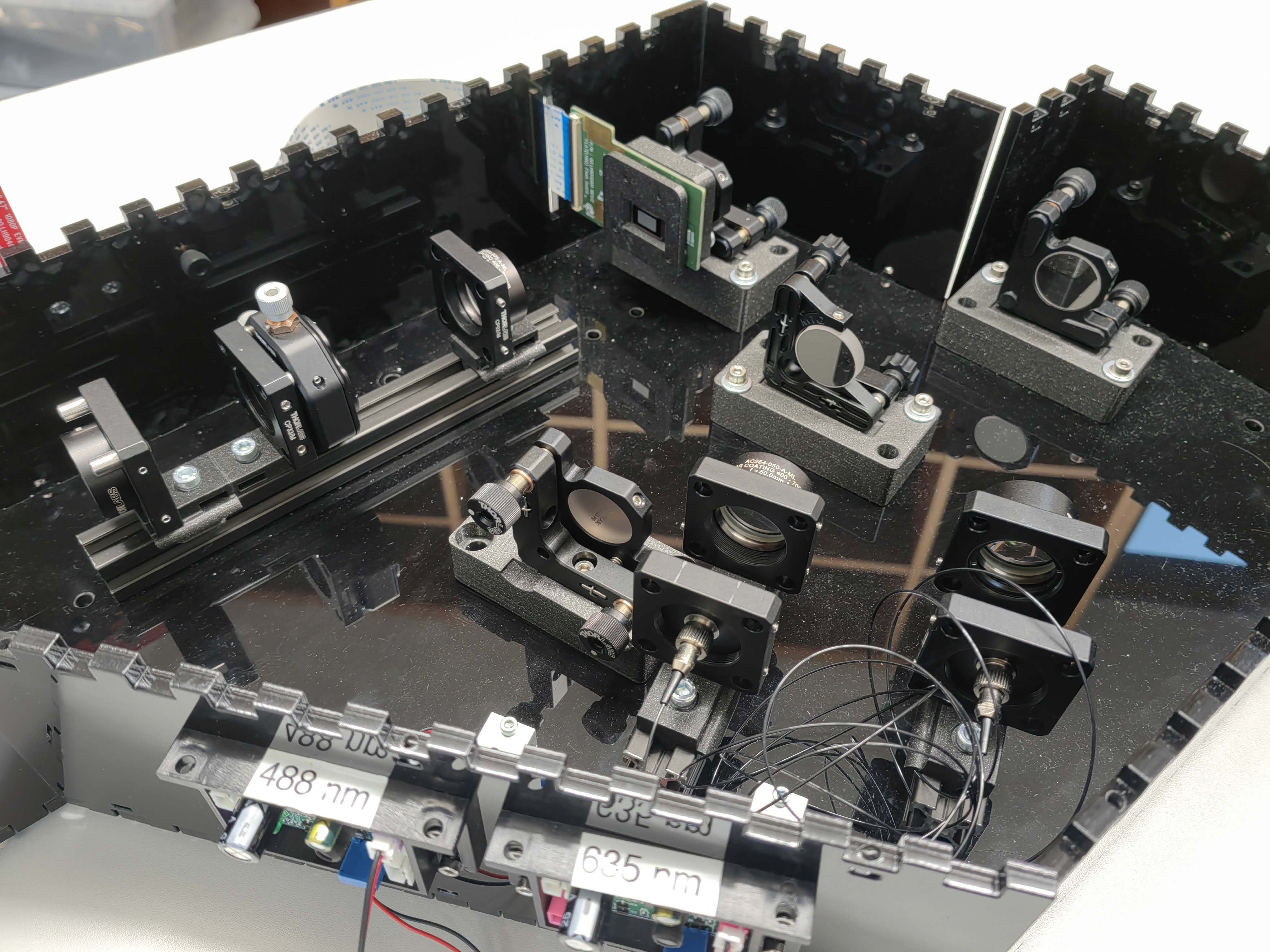
First hook the cage plate with fiber adapter onto the profile, then fix the laser diode cooling onto the ground board. Let the power cable for the laser go through the hole and mount the last side wall onto the board.
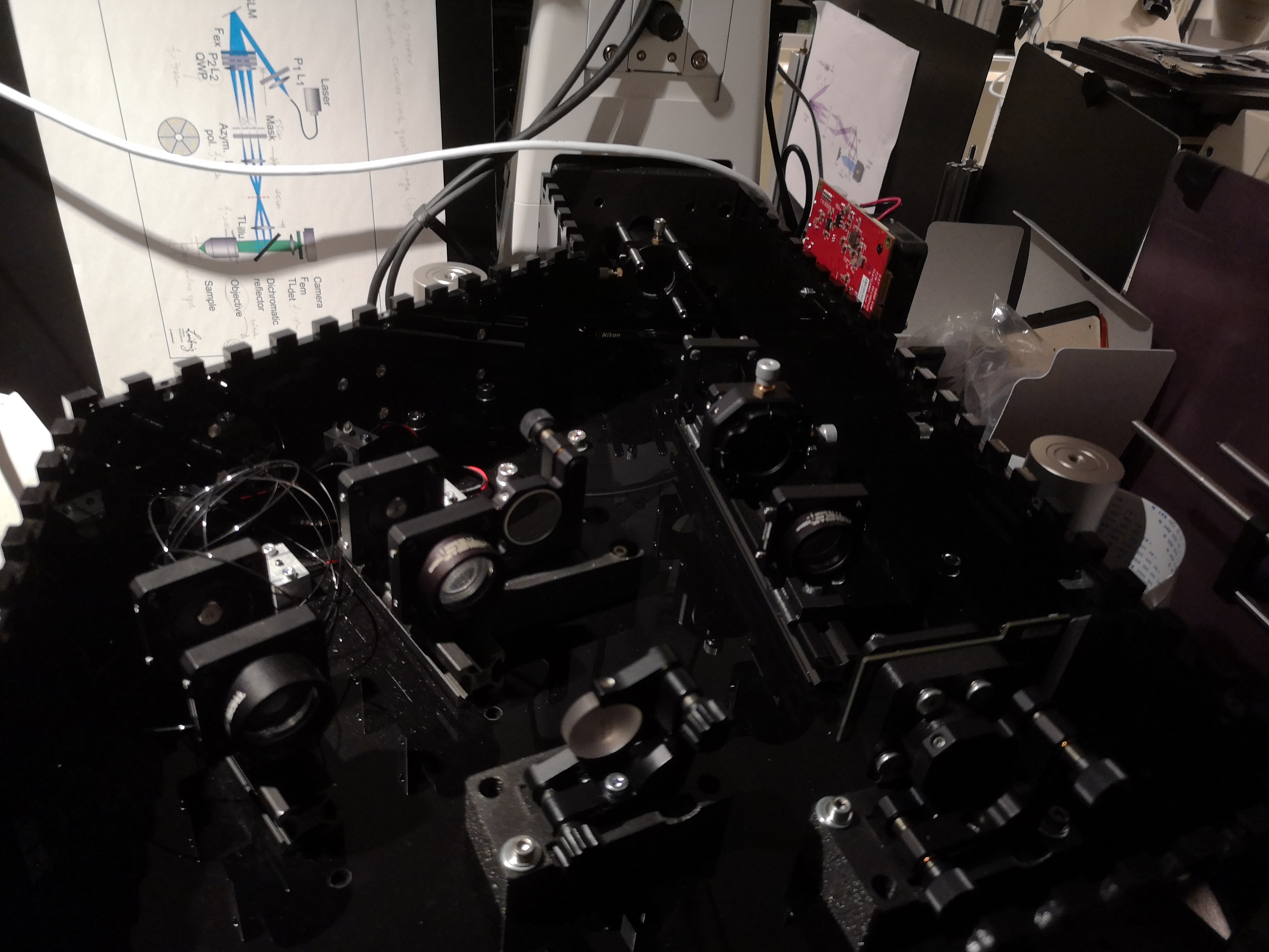
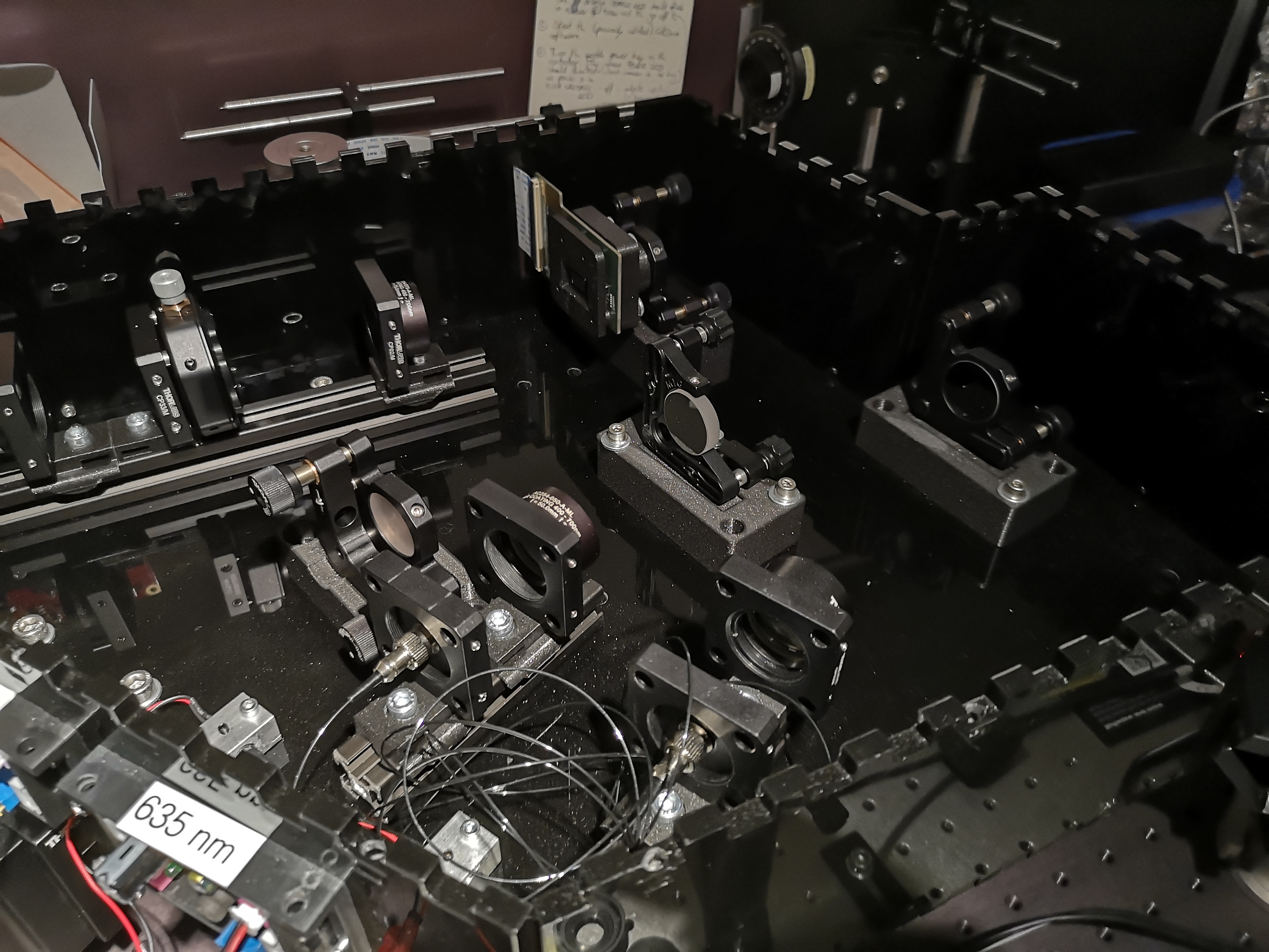
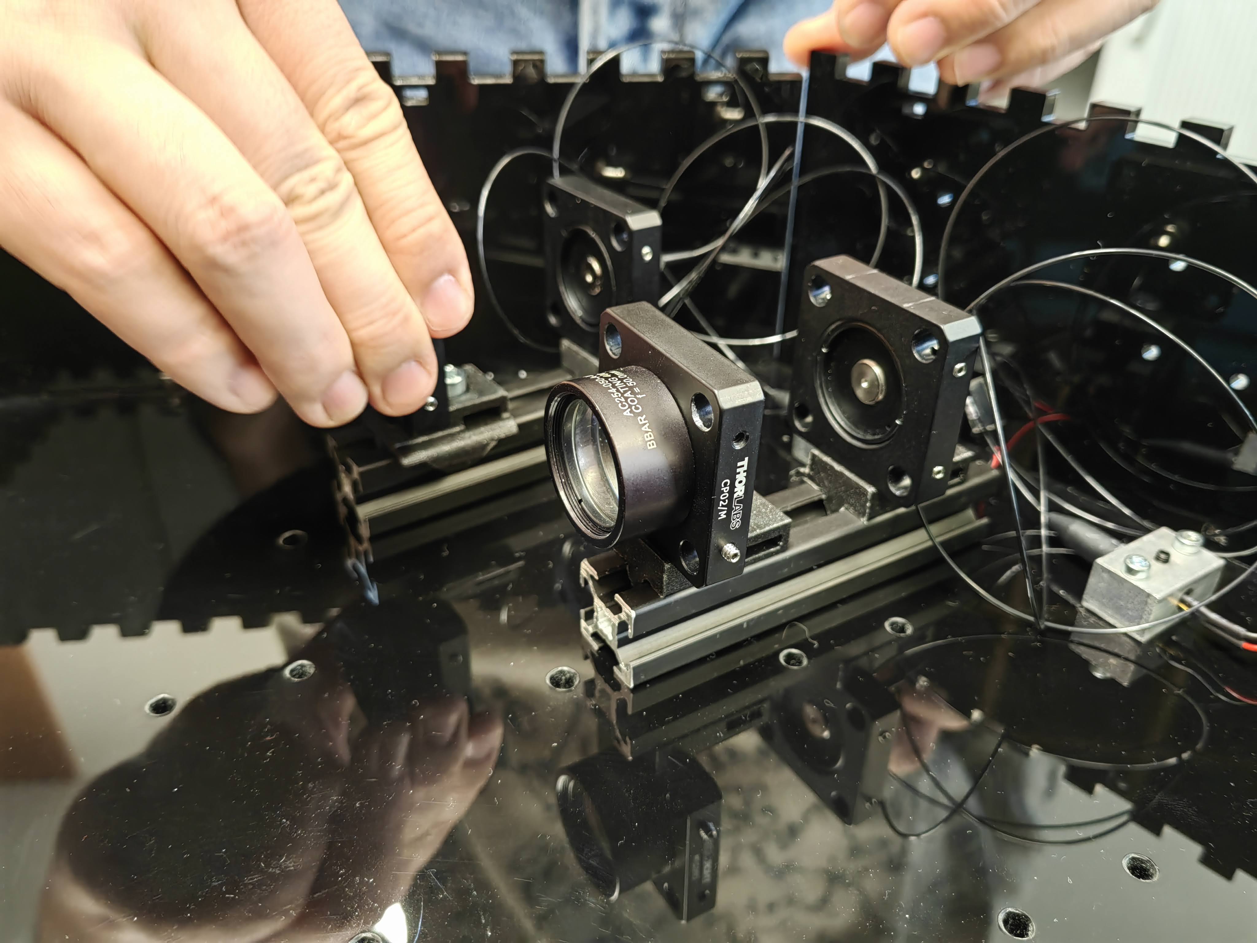
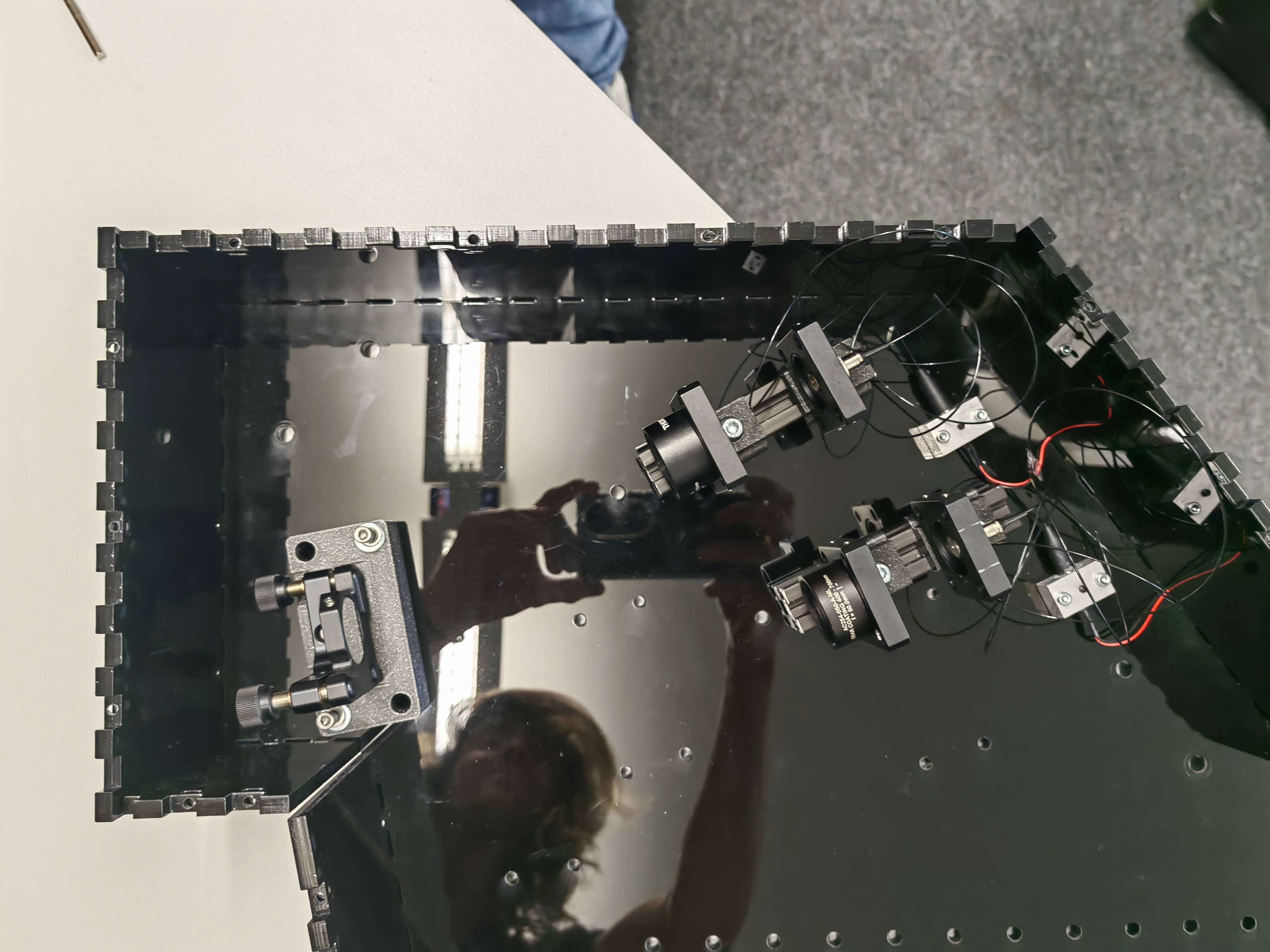
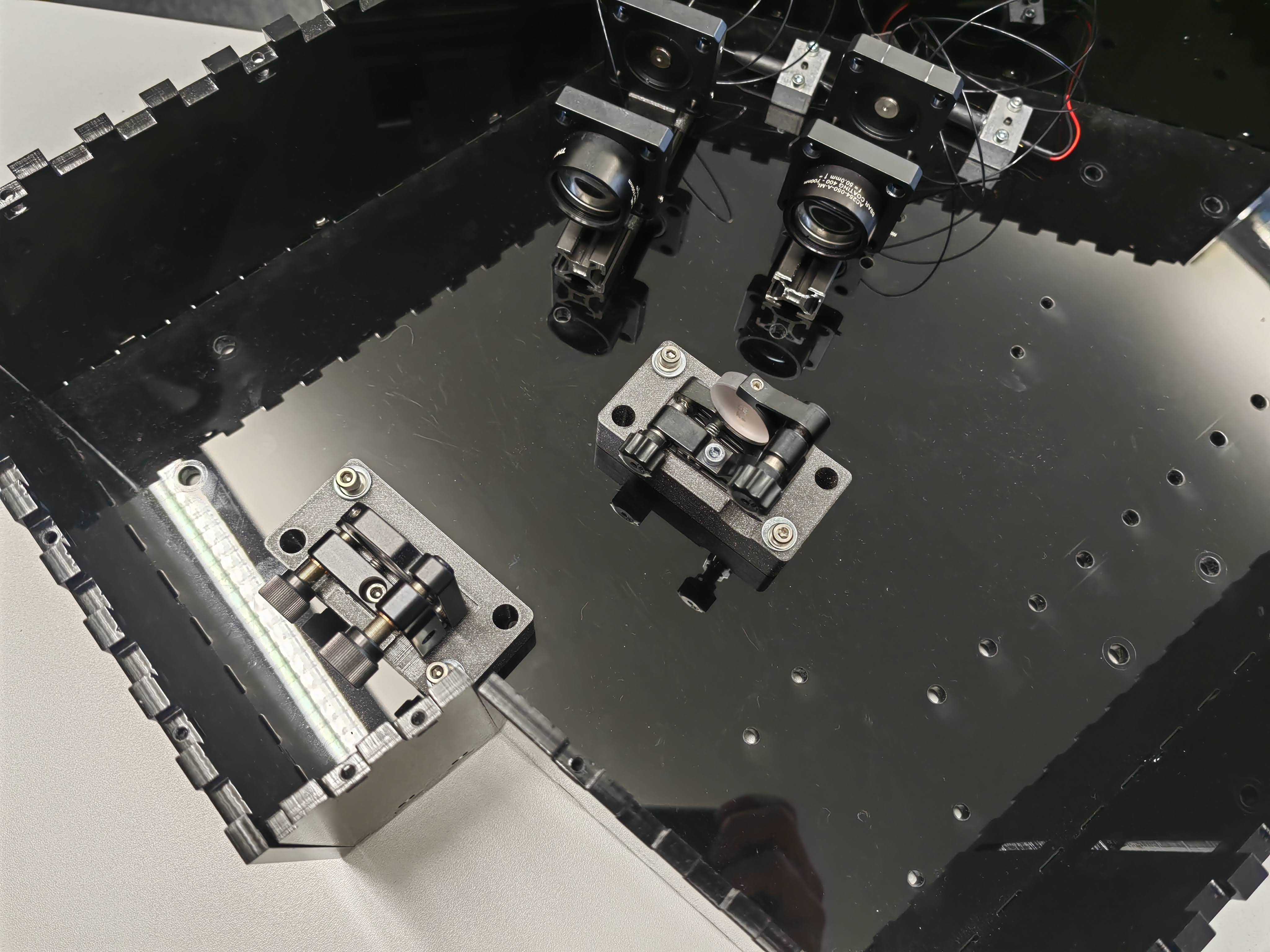
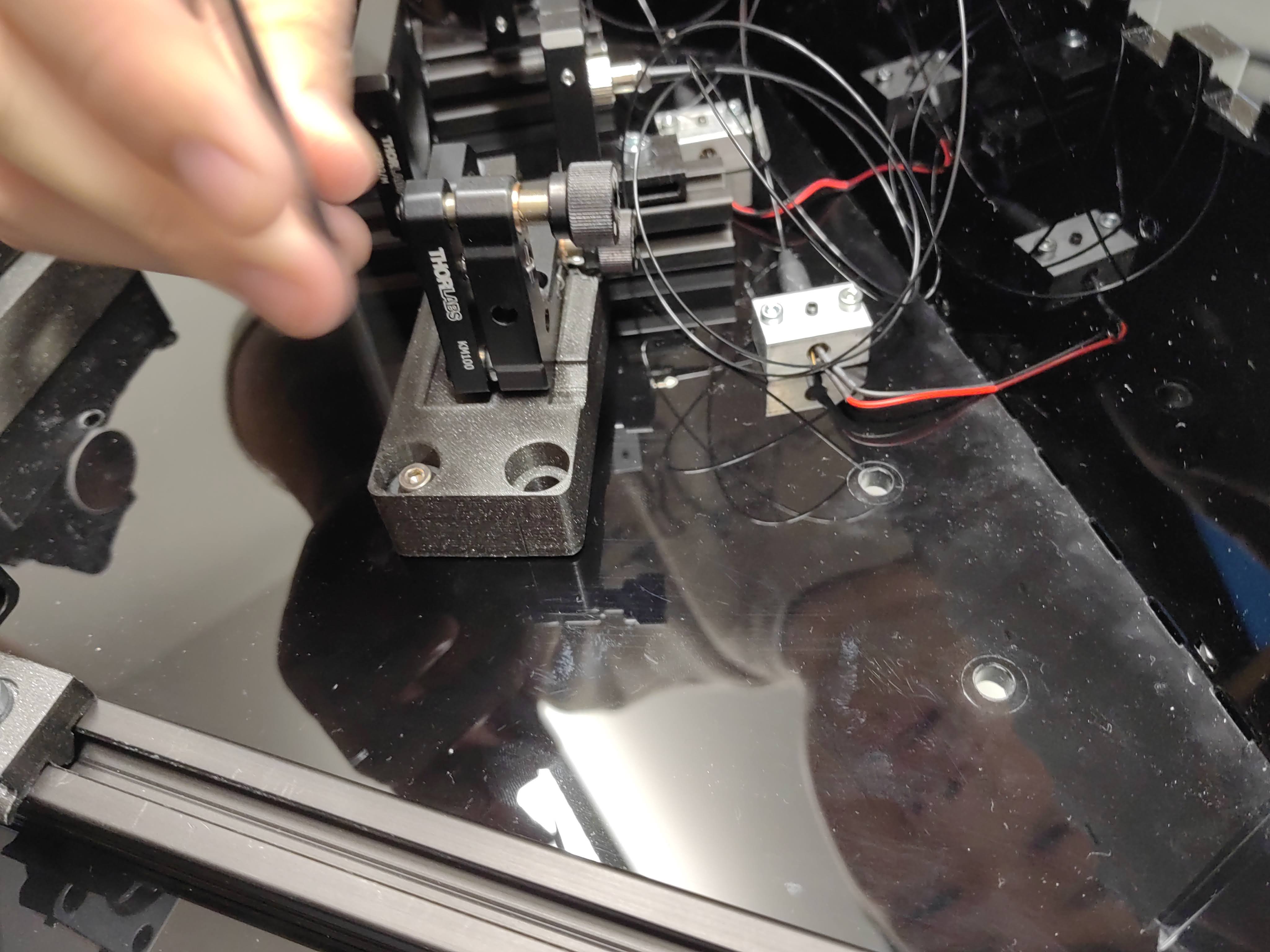
- Mounting guiding mirrors
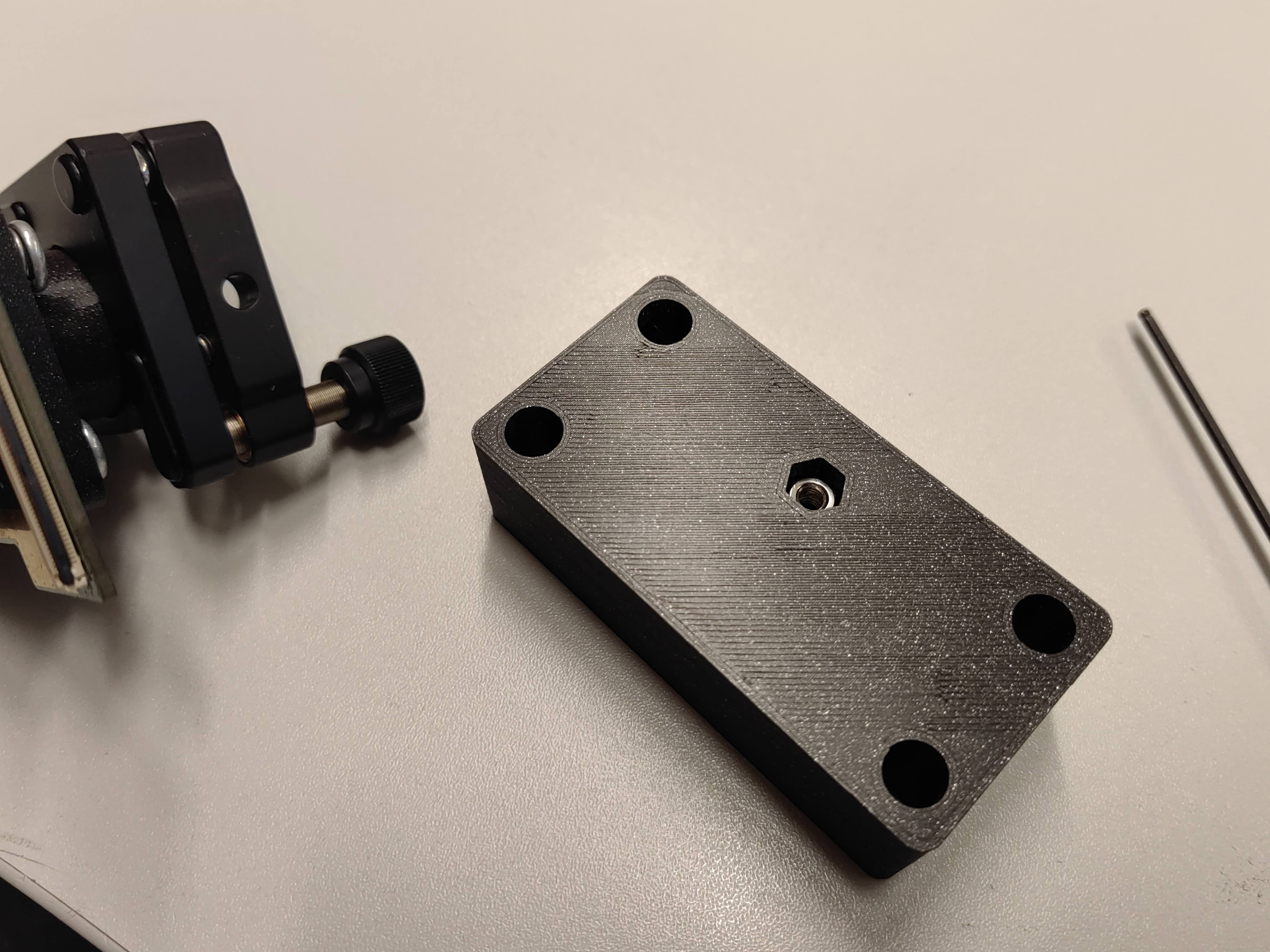
As in the previous step, mirrors and DMD are already mounted onto 3D printed base plate, on the ground board, there are holes to fix the base plates. M4 screws and washers are used for fixation, the hole on the 3D printed base plate is larger than M4 screw, in order to give the component still some possibility to position adjustment.
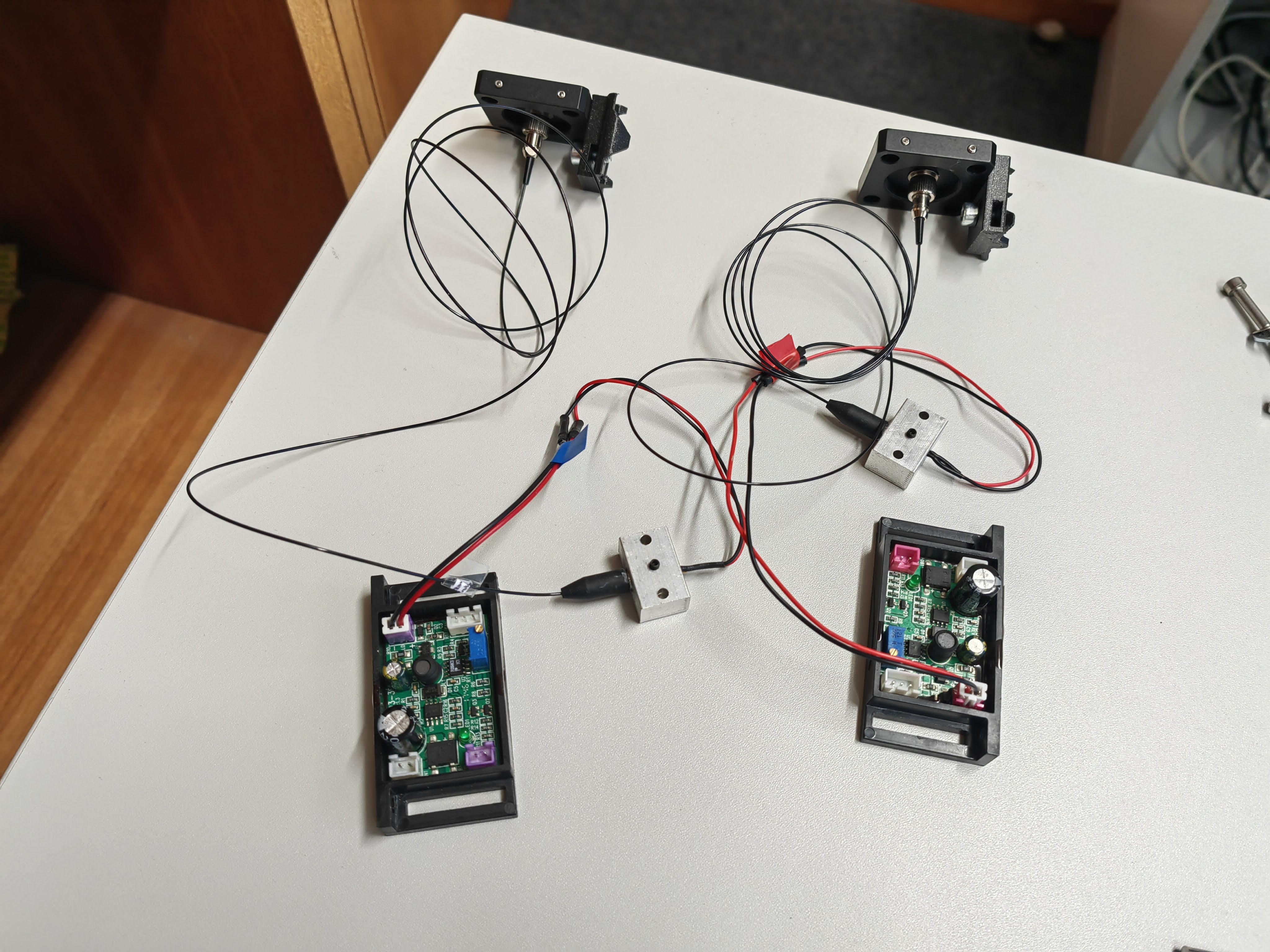
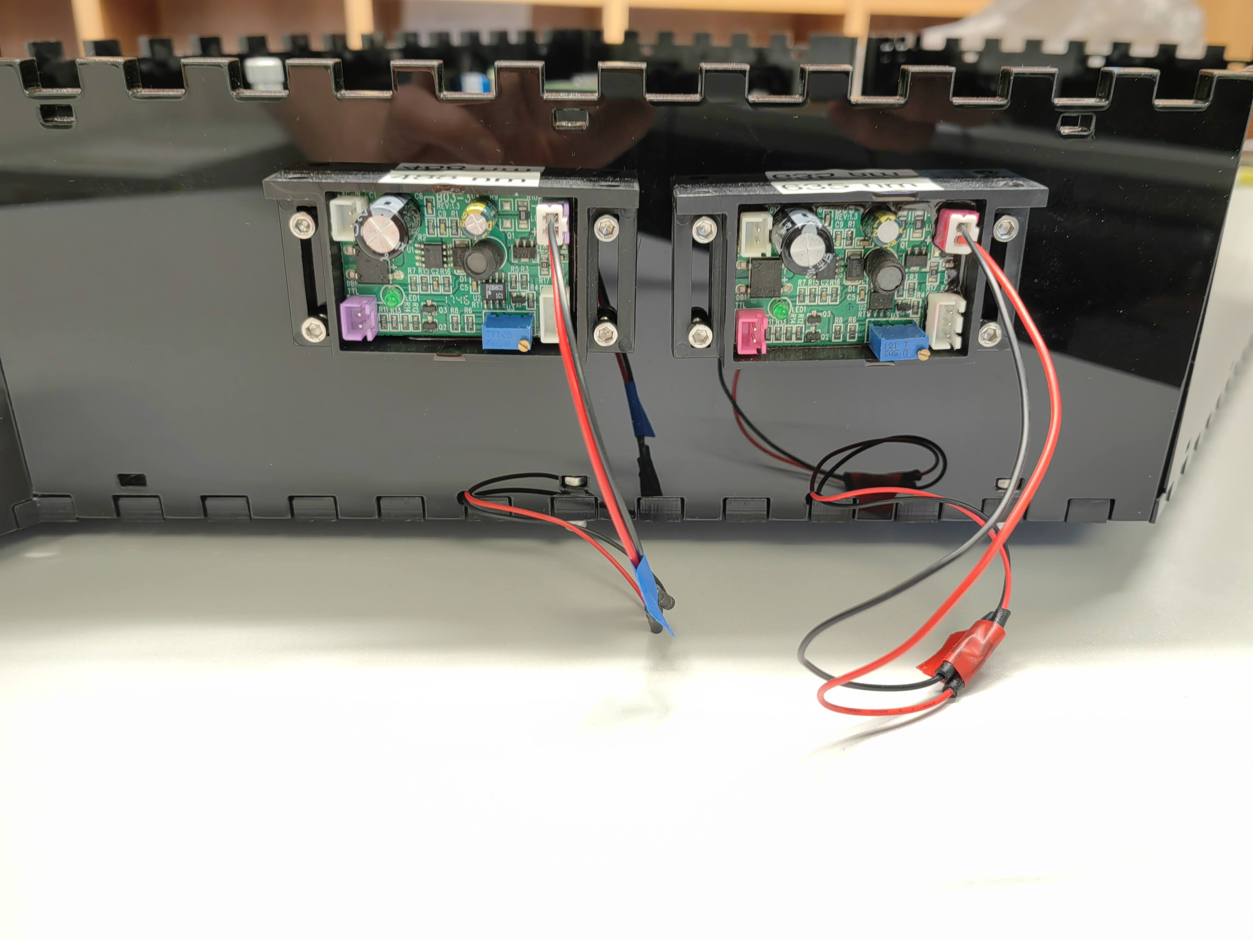
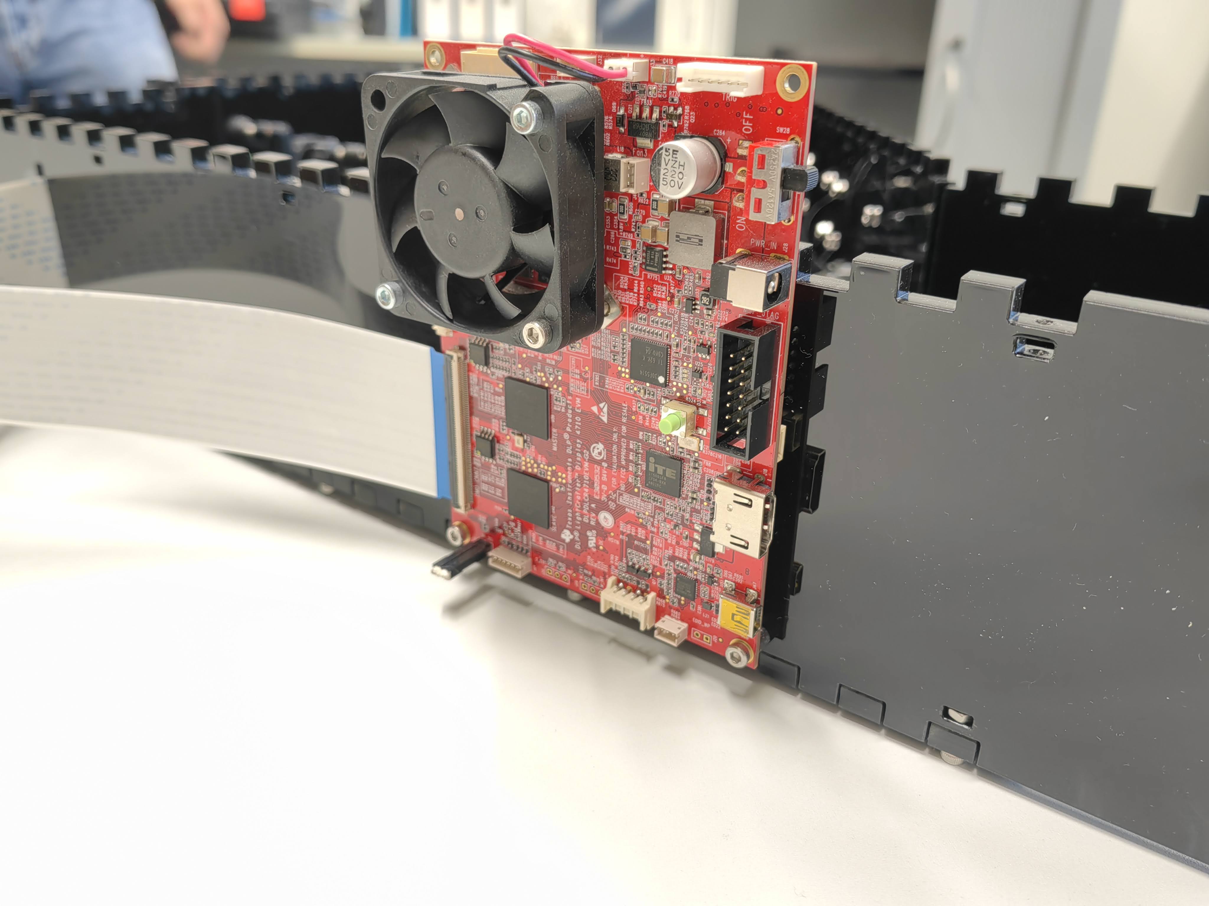
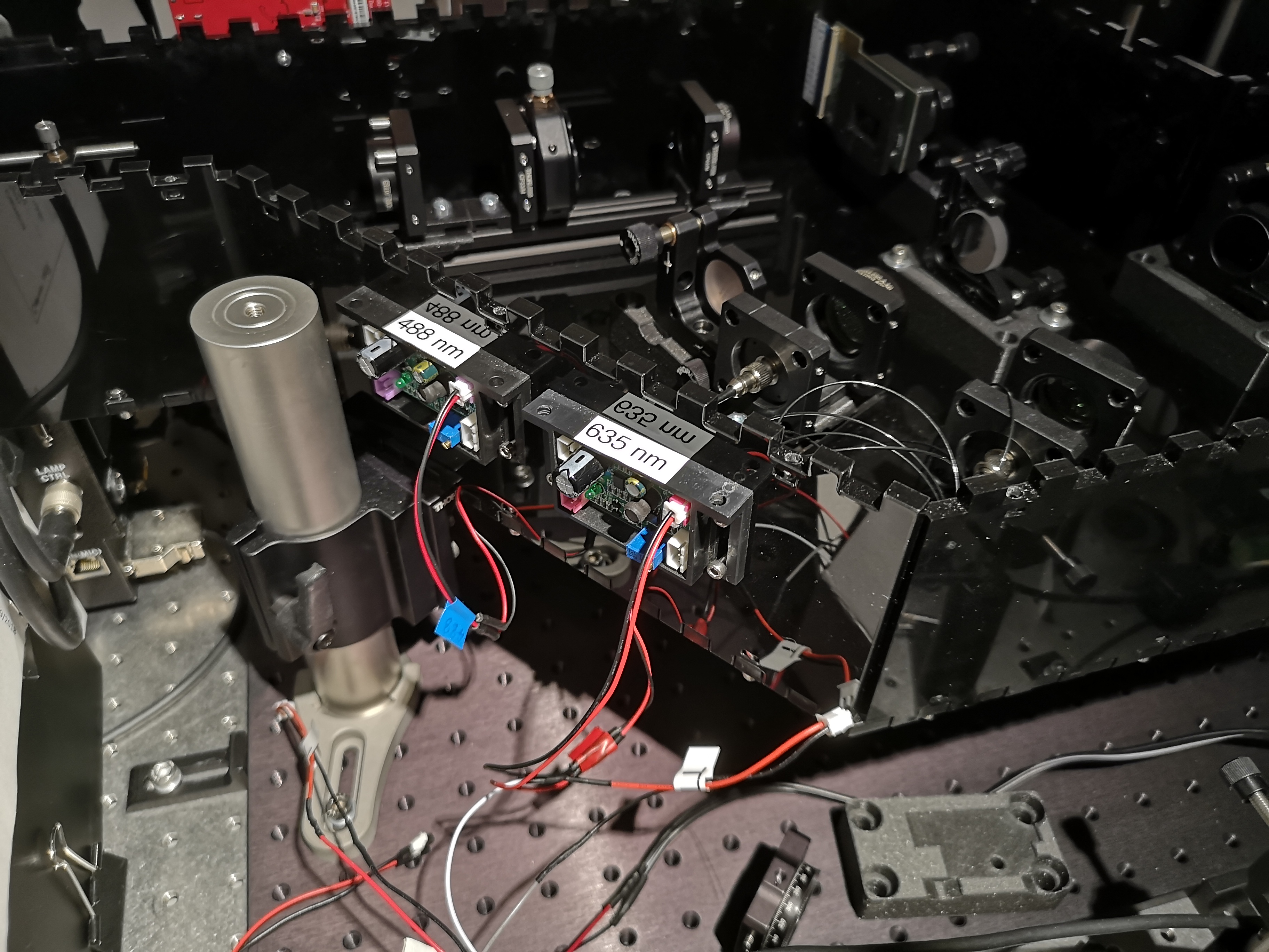
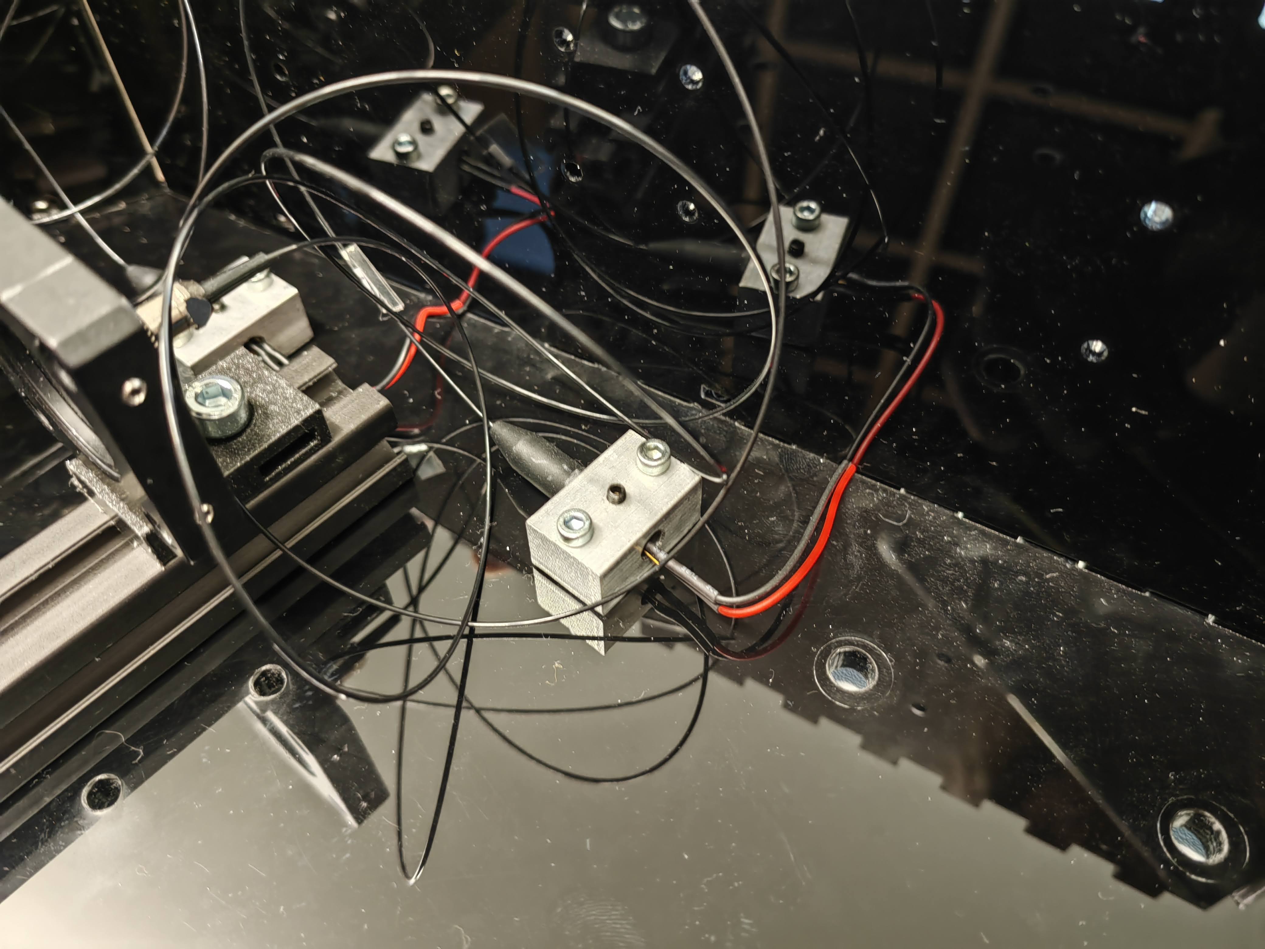
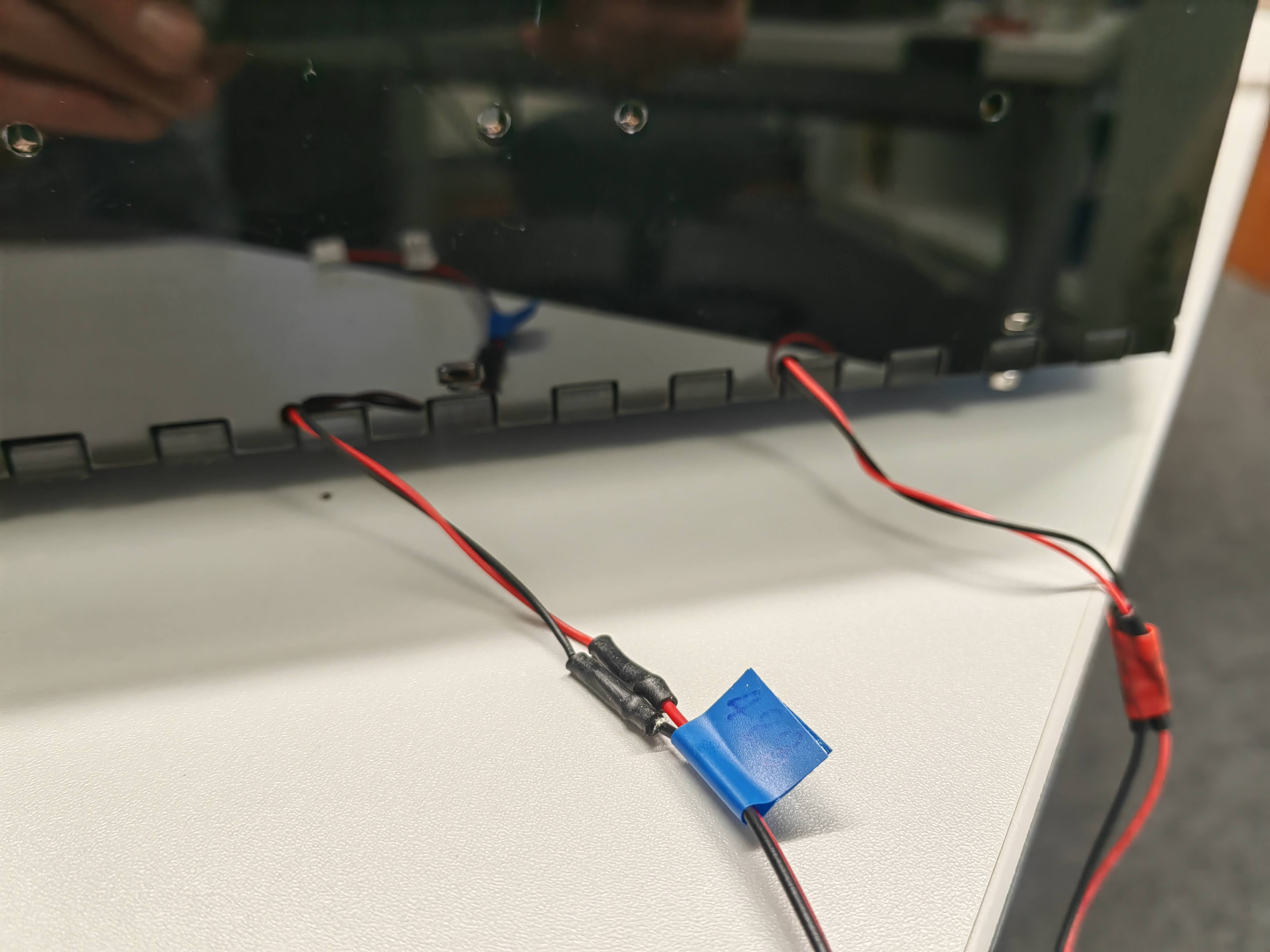
- Electrical wiring
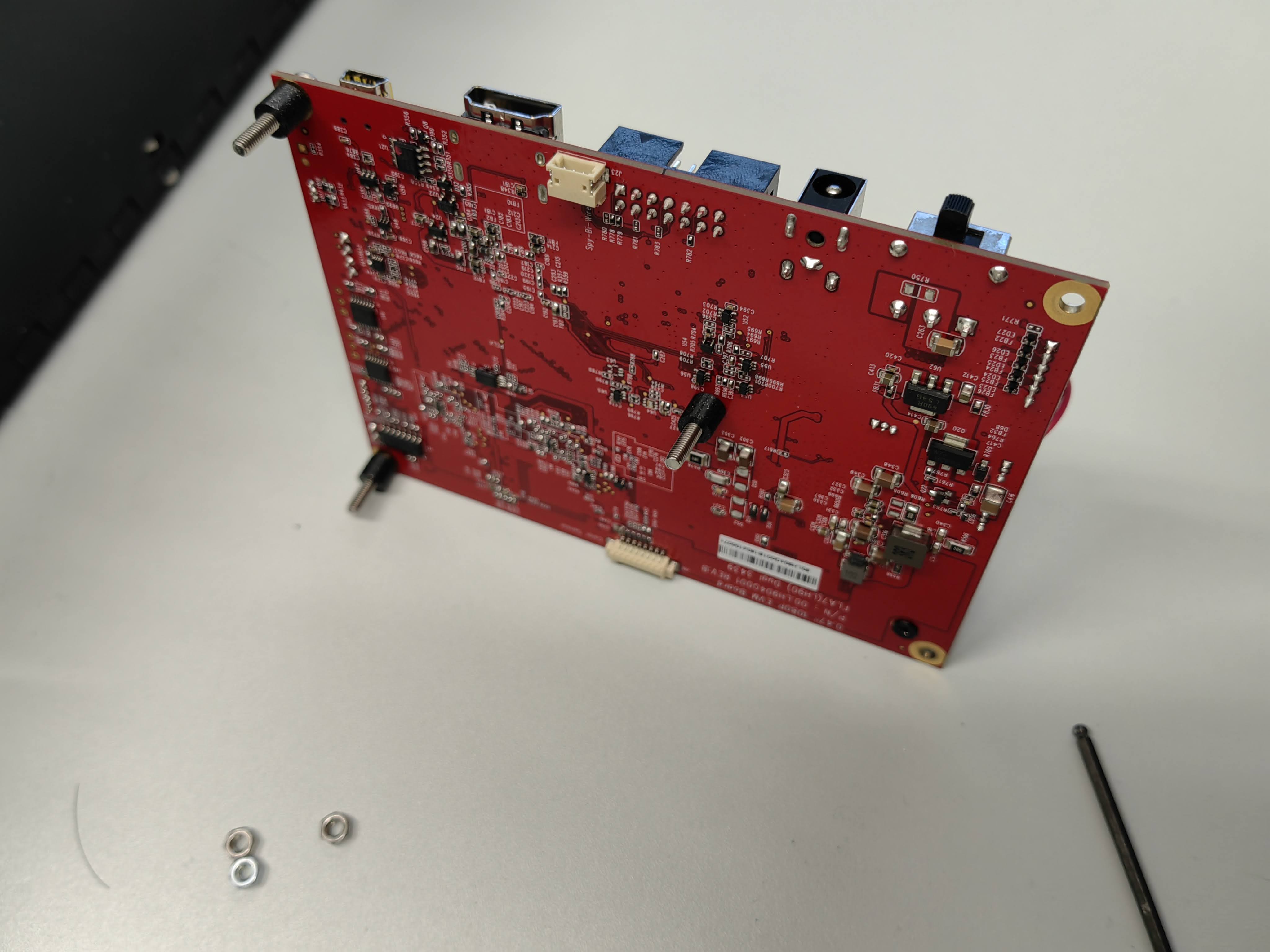
Connect DMD driver board to power supply and power it on, test if the DMD chip works without any problem.
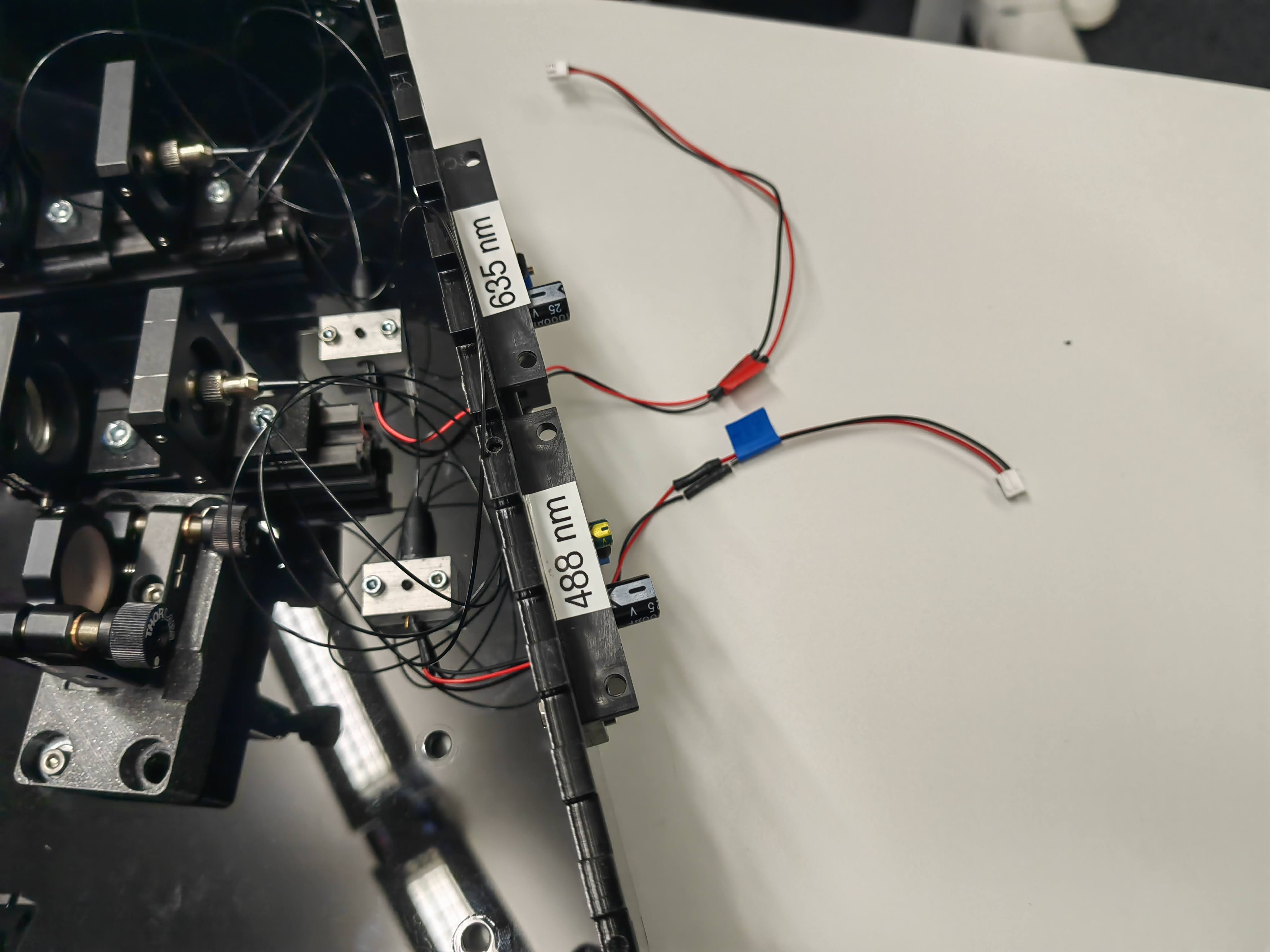
The both laser driver is sharing a 12V power supply, connect the power supply to one laser driver and the 12v fans output to the other driver. Now connect the lasers onto the driver board, check if the lasers works properly.
Connect ESP to the laser drivers for TTL signal
Now the setup is done with basic assembly, next step is to align the optical components.
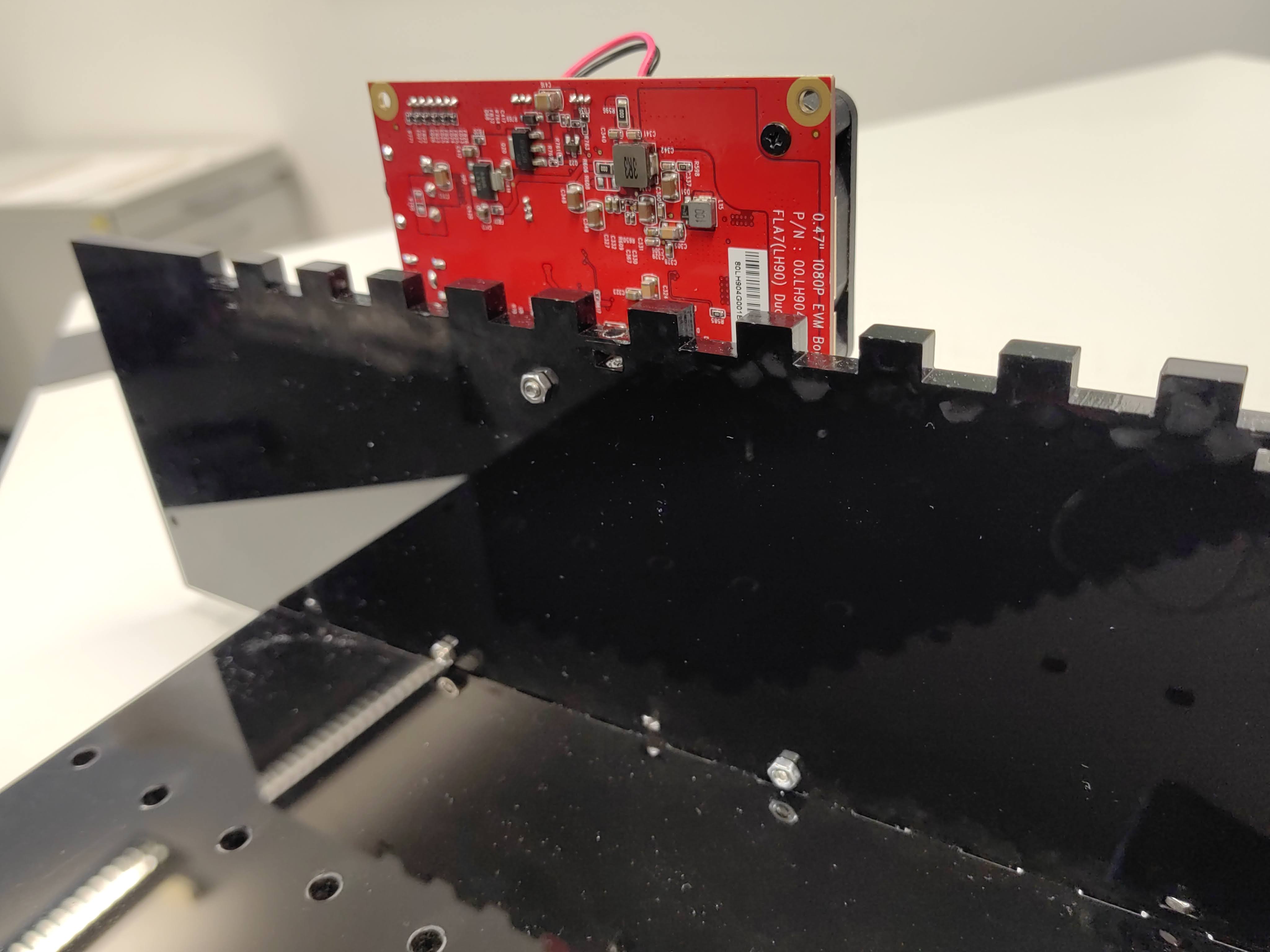
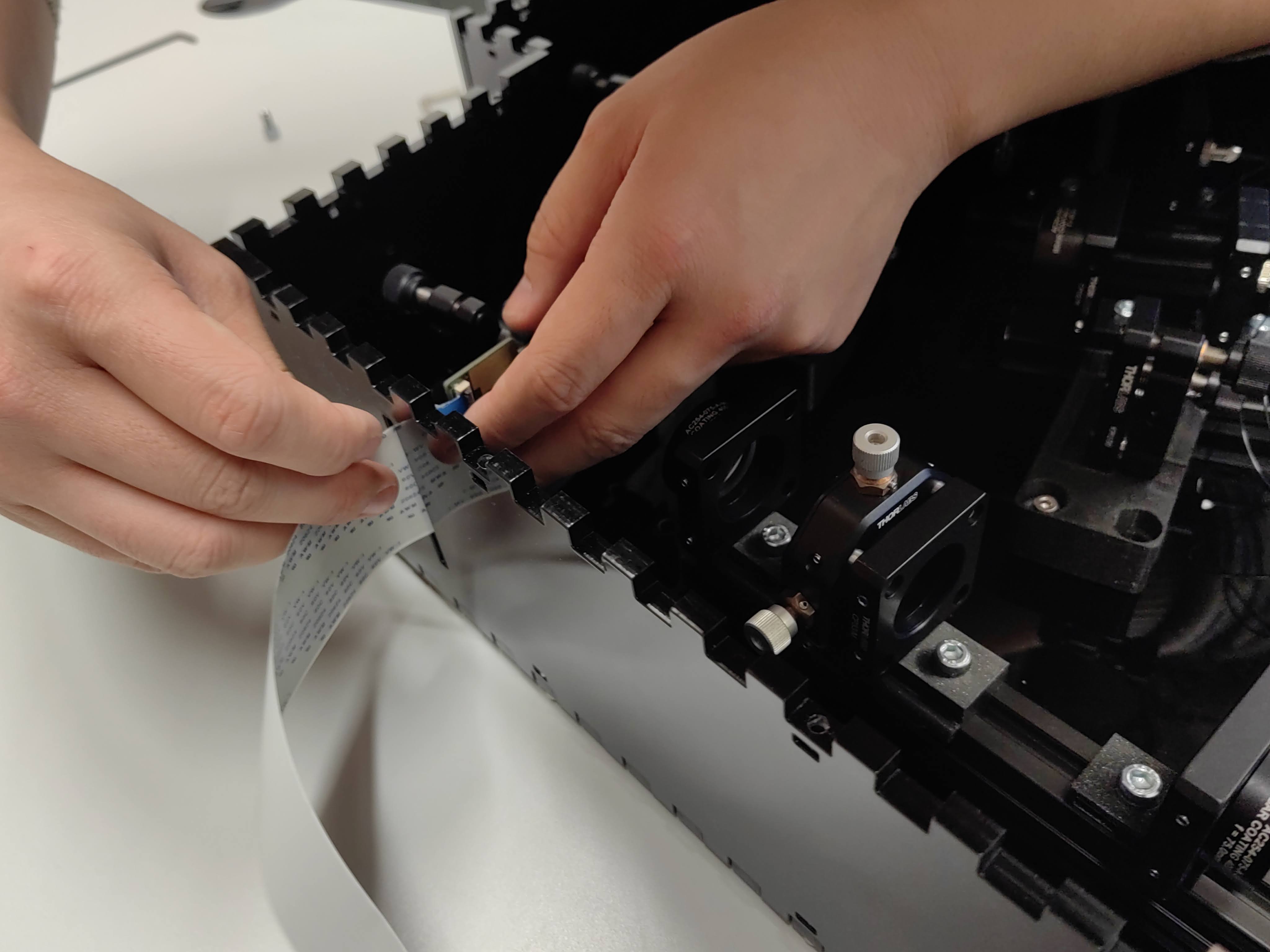
- Mounting DMD
Unsorted
| DMD | Fiber coupled laser |
|---|