Prepare the different parts
Preparation
This documentation is designed to help you replicate our setup and understand the components and files required for the project. The openSIMMO project integrates 3D printed parts, laser-cut enclosures, and various accessories to create a customizable optomechanical system. To replicate this setup, you will need to prepare components in the following categories: 3D printed parts, laser-cut enclosures, and accessories. Detailed design files can be found in the design-files repository.
Large Parts & Housing
The housing and large parts of the system are manufactured using laser cutting. Additionally, we use holders for commercial optomechanics, which are 3D printed to ensure system stability.
Optomechanics
To maintain system stability, certain optomechanical components with fine adjustabilities are necessary and cannot be replaced. We utilize a combination of Thorlabs parts and 3D printed components, including kinematic mirror mounts, 1-inch cage plates, and XY translation stages. An in-depth list of all the components used in our design can be found in the Bill of Materials.
3D Printing Files
All components were printed with 100% infill in PLA using a 0.2mm layer height on a Prusa i3 mk2.
- Download All 3D Printing Files: STL.zip
Table of 3D Printing Files
| File Name | Description |
|---|---|
| STL File | Kinematic mirror mounts x4 |
| STL File | DMD mount plate x1 |
| STL File | DMD assemblies cover x1 |
| STL File | Special mirror mount x1 |
| STL File | Camera mount x1 |
| STL File | Nikon Adapter |
| STL File | Ray optics mounts x7 |
| STL File | Raspberry Pi 2 top cover x1 |
| STL File | Raspberry Pi 3 bottom cover x1 |
Lasercutting Files
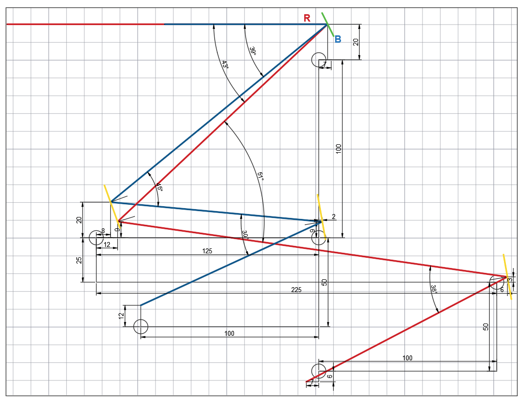
The different optical elements are fixed in place according to the provided sketch.
- Lasercutting Files Location: LaserCutting folder
| File Name | Quantity | Description |
|---|---|---|
| Ground board with mounting holes | x1 | Base plate with mounting holes for the setup |
| Side walls, Back2, Back3, Laser, LaserDriver, Mirror, Telescope, TelescopeDown | x7 | Side walls for enclosing the system and mounting various components. Includes specific walls for laser, laser driver, mirror, and telescope alignments |
Design Files
The components are constructed using Inventor 2024 Student edition.
- Design Files Location: INVENTOR folder
Fourier mask
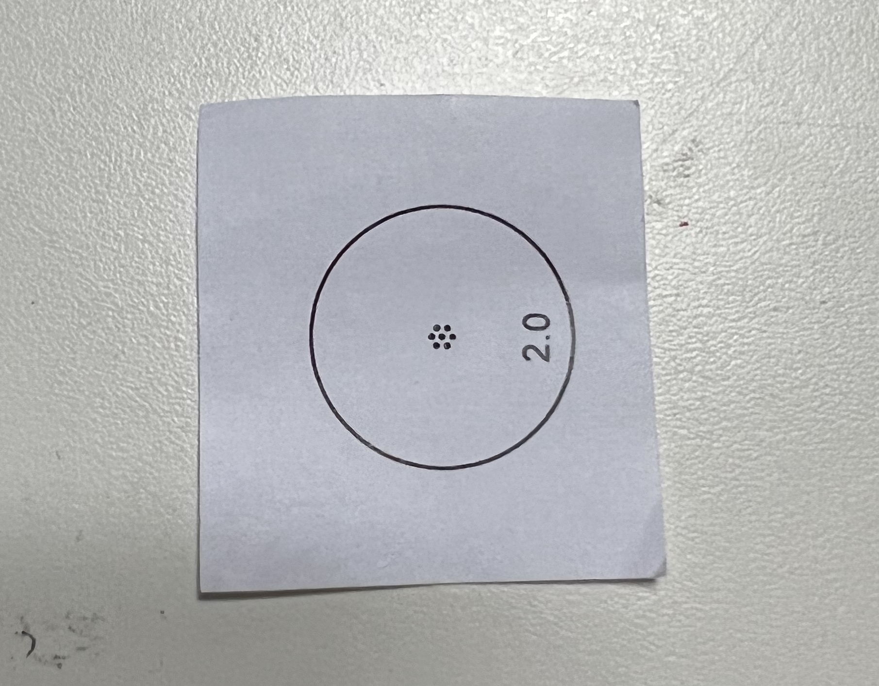
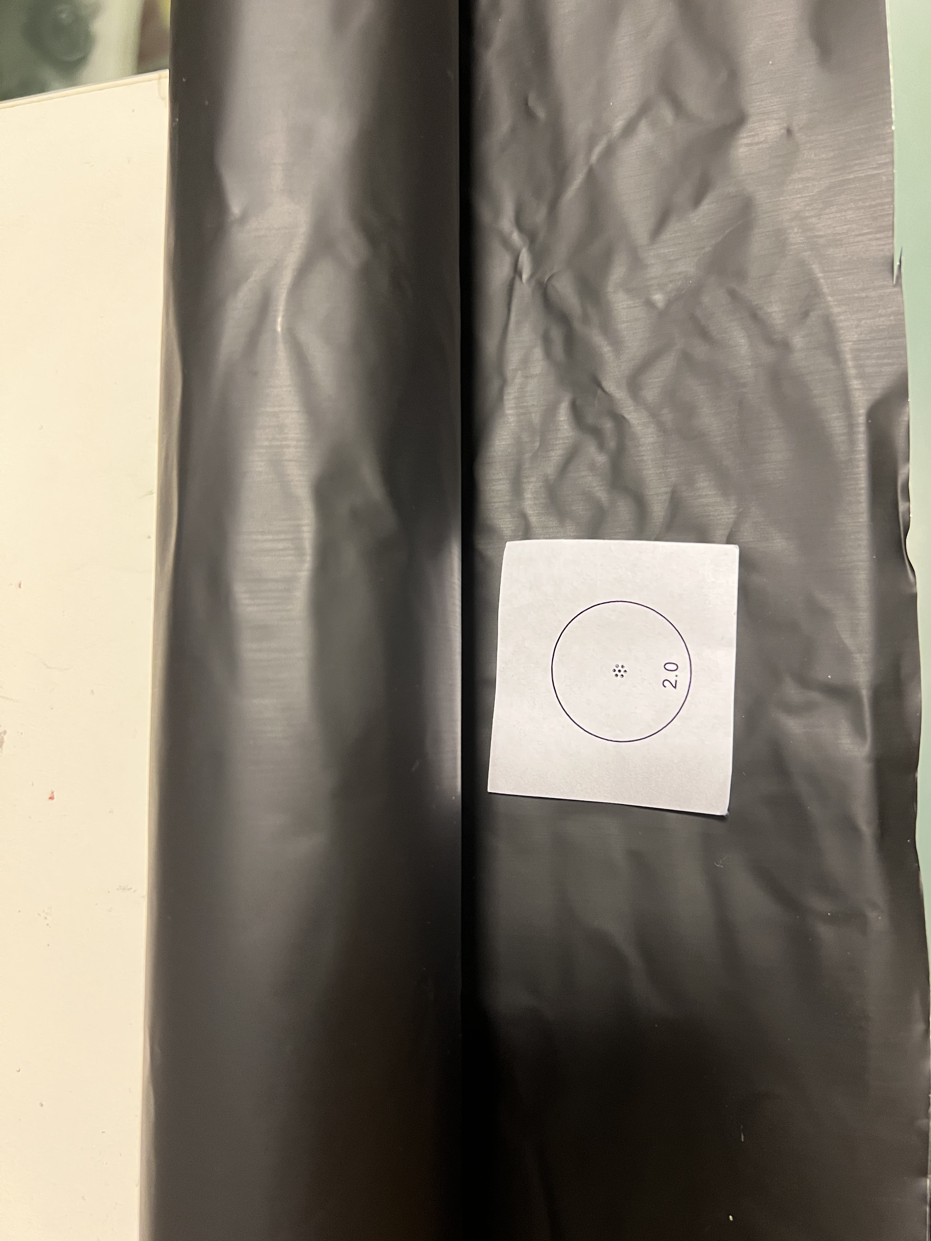
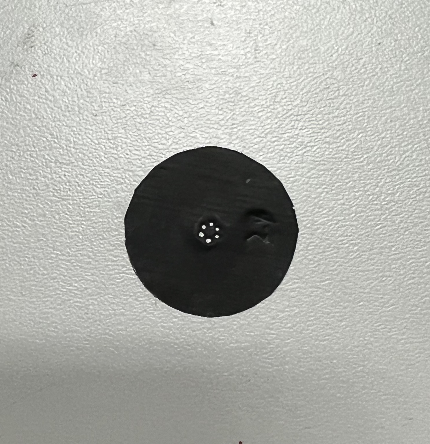
The Fourier mask is used to block the 0th order beam, only 1st order beam can pass through for creating 2 beam SIM interference. The Fourier mask was made with Thorlabs black aluminium foil. The hole position was made with AutoCAD and exported as pdf file. Printing the pattern with normal printer and cut the black aluminium foil with 25mm diameter circle, using a pin to stich the 6 holes on the right position.
Accessories
The setup also uses 3 standard aluminum profiles to mount the ray optical parts, with lengths of 2 x 100mm and 1 x 150mm.
For further information or if you have any questions, feel free to open an issue in this repository.